Project 1.1.5: Triple LEDS
| Description | This is the project where you’ll program three LEDS to turn on at the same time. |
|---|---|
| Use case | Looking at our streetlights, we normally have more lights on at the same time. This is what you are going to imitate with just three LEDS. |
Components (Things You will need)
 |
 |
 |
 |
 |
|---|---|---|---|---|
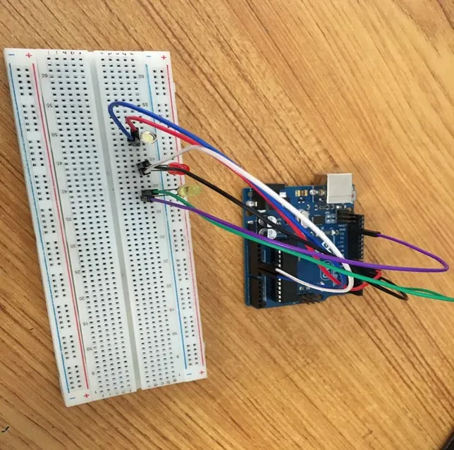
Building the circuit
Things Needed:
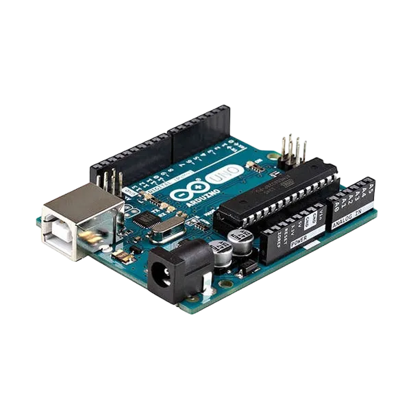
- Arduino Uno = 1
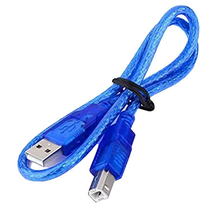
- Arduino USB cable = 1
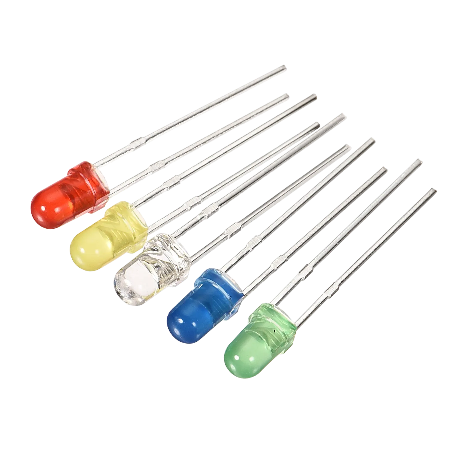
- White LED = 1
- Red LED = 1
- Yellow LED = 1
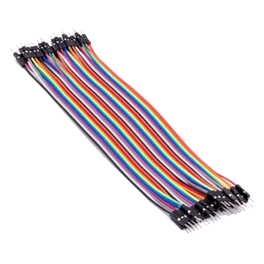
- Red jumper wires = 1
- Blue jumper wires = 1
- Black jumper wires = 1
- White jumper wires = 1
- Green jumper wires = 1
- Purple jumper wires = 1
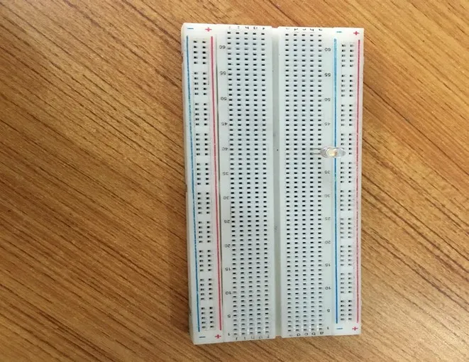
Mounting the component on the breadboard
Mounting the component on the breadboard
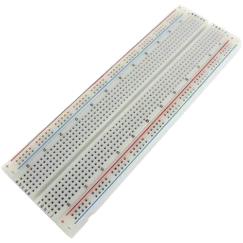
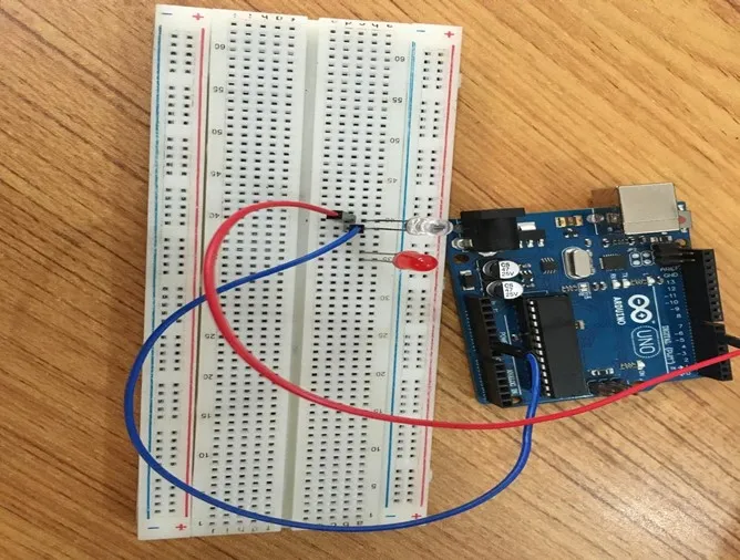
Step 1: Take the breadboard, the white LED and insert it into the vertical connectors on the breadboard.
 .
.
NB: Make sure you identify where the positive pin (+) and the negative pin (-) is connected to on the breadboard. The longer pin of the LED is the positive pin and the shorter one, the negative PIN.
WIRING THE CIRCUIT
Things Needed:
- Red male-male-to-male jumper wires = 1
- Black male-to-male jumper wires = 1
- White male-to-male jumper wires = 1
- Blue male-to-male jumper wires = 1
Step 2: Connect one end of red male-to-male jumper wire to the positive pin of the white LED on the breadboard and the other end to hole number 6 on the Arduino UNO.
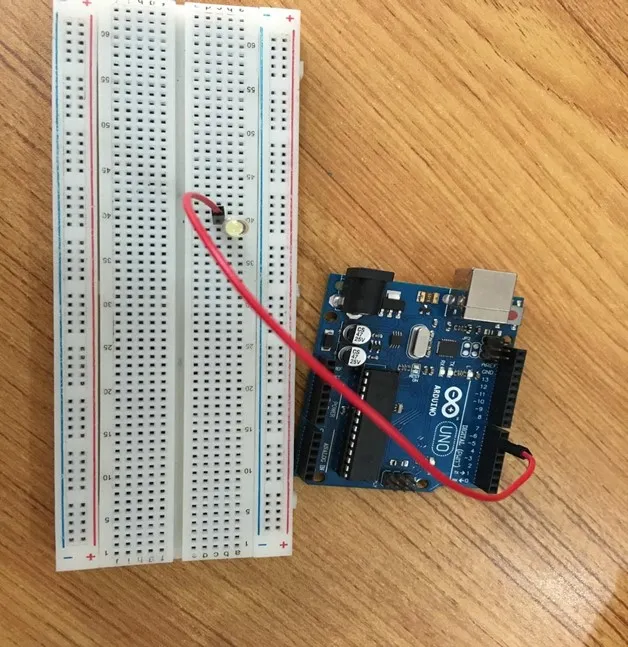 .
.
Step 3: Connect one end of the blue male-to-male jumper to the negative pin of the white LED on the breadboard and the other end to GND on the Arduino UNO.
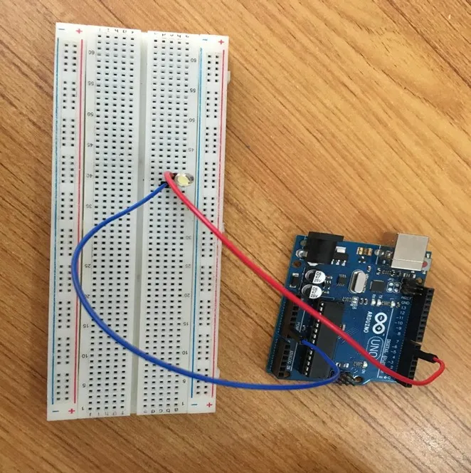 .
.
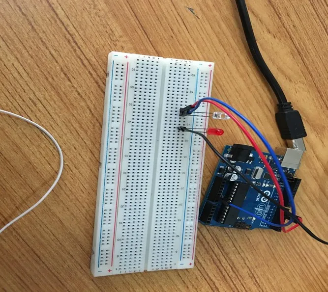
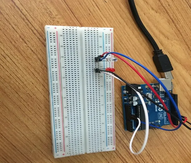
Step 4: Take the red LED and insert it into the vertical connectors on the breadboard.
 .
.
Step 5: Connect one end of the black male-to-male jumper wire to the positive pin of the red LED on the breadboard and the other end to hole number 5 on the Arduino UNO.
Step 6: Connect one end of the black male-to-male jumper wire to the positive pin of the red LED on the breadboard and the other end to hole number 5 on the Arduino UNO.
 .
.
Step 7: Connect one end of the white male-to-male jumper wire to the negative pin of the white LED on the breadboard and the other end to GND on the Arduino UNO.
 .
.
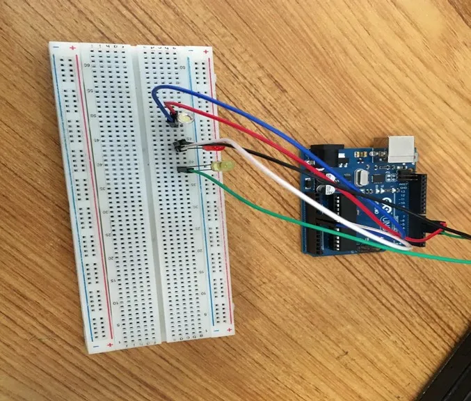
Step 8: Take the yellow LED and insert it into the vertical connectors on the breadboard.
 .
.
Step 9: Connect one end of the green male-to-male jumper wire to the positive pin of the yellow LED on the breadboard and the other end to hole number 4 on the Arduino UNO.
 .
.
Step 10: Connect one end of the purple male-to-male jumper wire to the negative pin of the yellow LED on the breadboard and the other end to GND on the Arduino UNO.
 .
.
make sure you connect the arduino usb use blue cable to the Arduino board.
PROGRAMMING
Step 1: Open your Arduino IDE. See how to set up here: Getting Started.
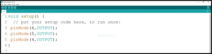
Step 2: Type the following codes in the void setup function as shown in the image below.
 .
.
NB: pinMode will help the Arduino board to decide which port should be activated. The code below will turn off the three light bulbs.
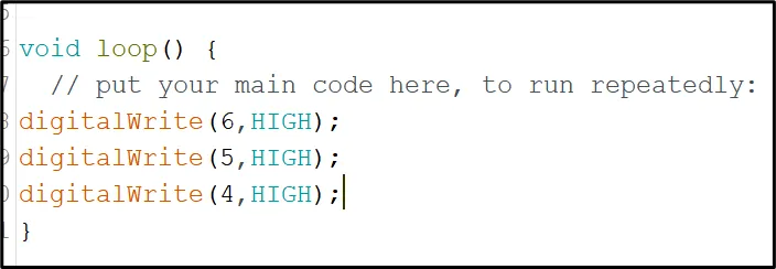
Step 3: Type the following codes in the void loop function.as shown in the image below;
 .
.
_NB: To turn this LEDS off, you can change the “HIGH” in the ode into “LOW” _
Step 4: Save your code. See the Getting Started section
Step 5: Select the arduino board and port See the Getting Started section:Selecting Arduino Board Type and Uploading your code.
Step 6: Upload your code. See the Getting Started section:Selecting Arduino Board Type and Uploading your code
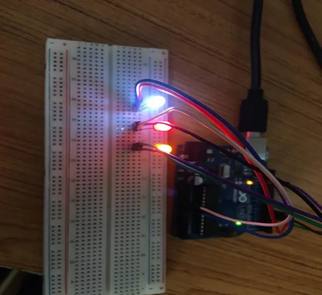
OBSERVATION
 .
.
CONCLUSION
To summarize, the project focused on simultaneously illuminating three LEDs without any blinking demonstrates a core understanding of parallel LED control. By activating all three LEDs concurrently, participants learn about basic circuitry connections and the concept of multiple output coordination. This project lays a cornerstone for more intricate electronics projects while highlighting the importance of synchronized actions, fostering curiosity and skills in the field of practical electronics.