Project 2.5.2: LED Control with Arduino and Push Button
| Description | You will learn how to create a simple circuit using an Arduino microelectronic and a push button. |
|---|---|
| Use case | Imagine you want to create an interactive lighting system for your living room using Arduino and push buttons. You want to control the ambiance by turning on specific lights with a simple press of a button |
Components (Things You will need)
 |
 |
 |
 |
 |
 |
|---|---|---|---|---|---|
Building the circuit
Things Needed:
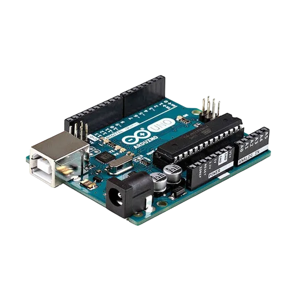
- Arduino Uno = 1
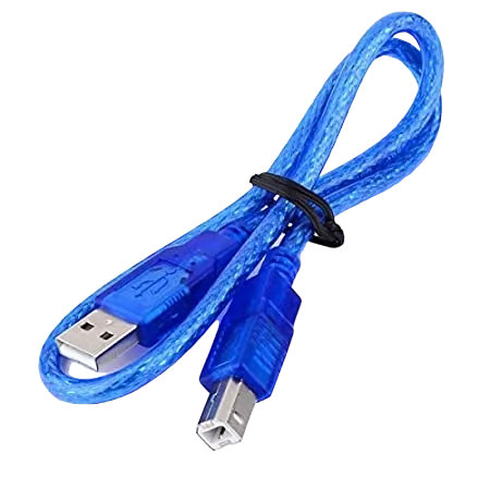
- Arduino USB cable = 1
- Resistor = 1
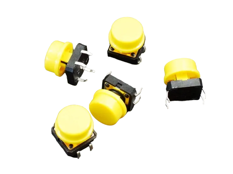
- Push button = 1
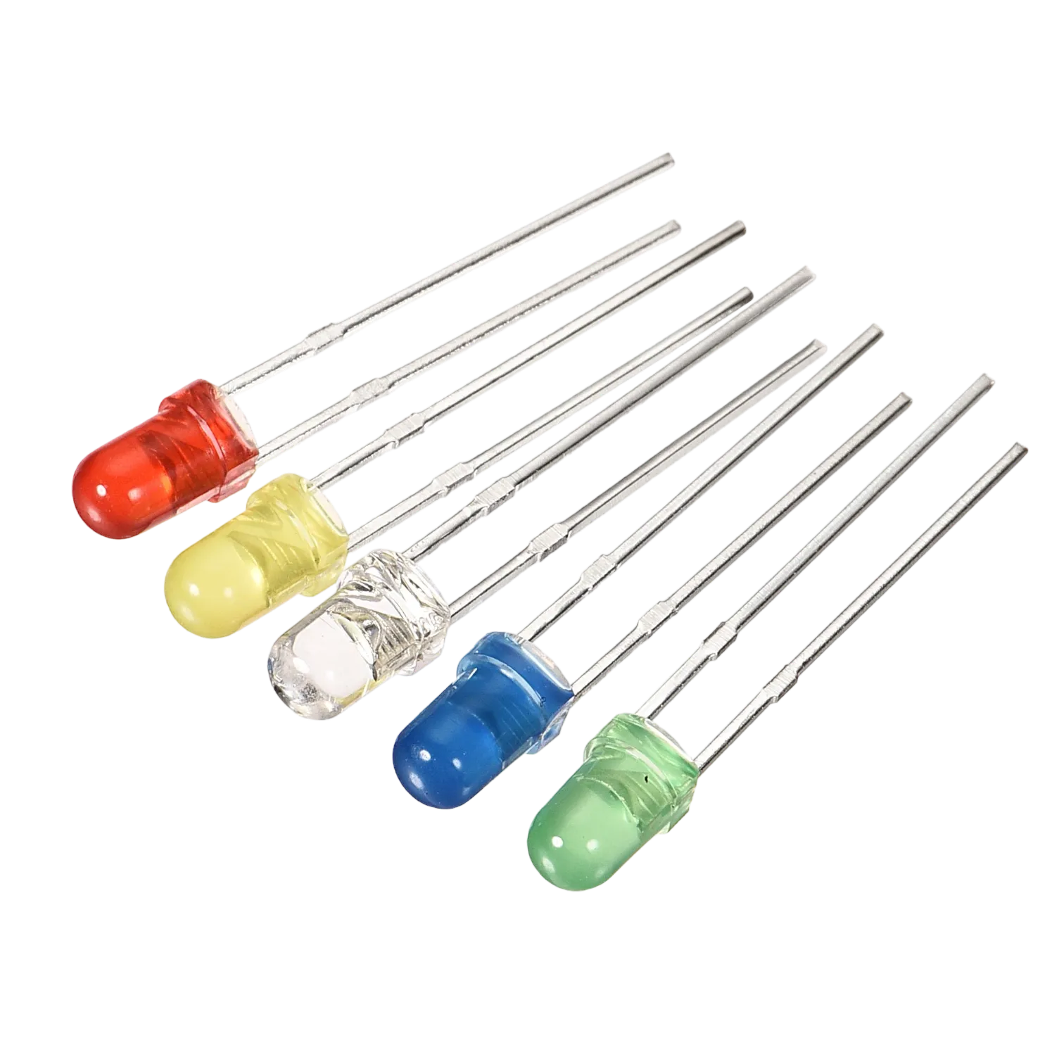
- Red LED = 1
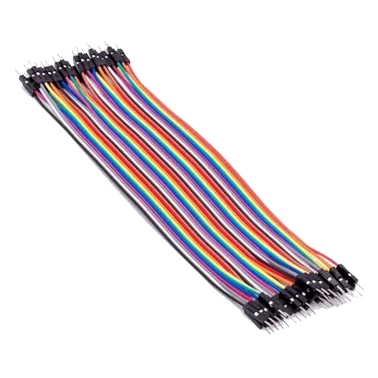
- Blue jumper wire= 1
- Yellow jumper wire= 1
- Black jumper wire= 1
- Red jumper wire= 1
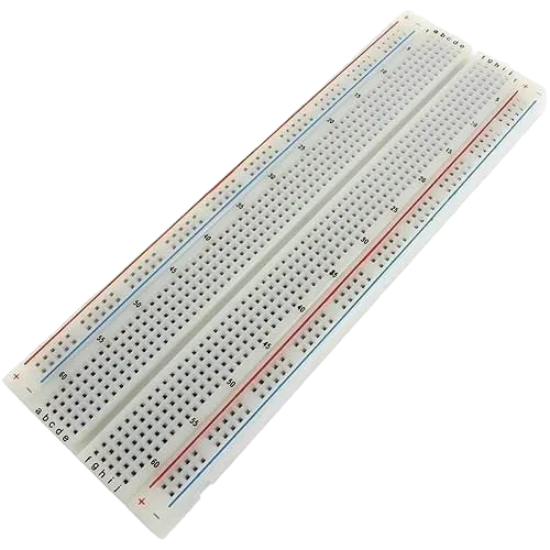
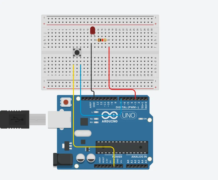
Mounting the component on the breadboard
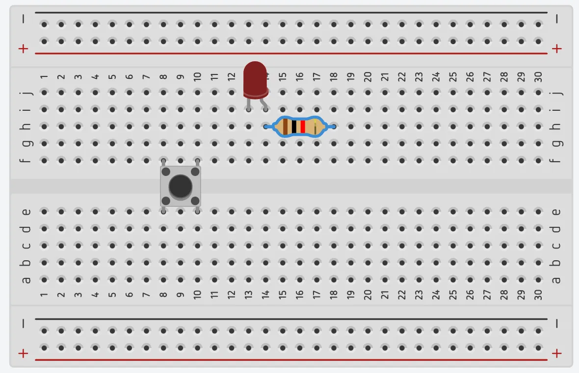
Step 1: Take the breadboard and the red LED and insert the red LED into the vertical connectors on the breadboard.
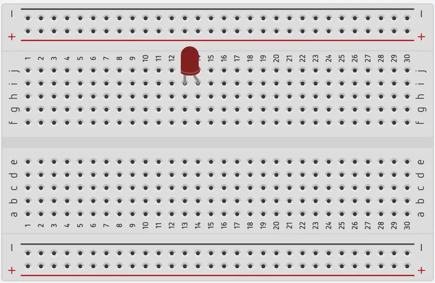 .
.
step 2: Connect the pushbutton on the breadboard but make sure the two pair of the pins are connected on each side of the bridge.
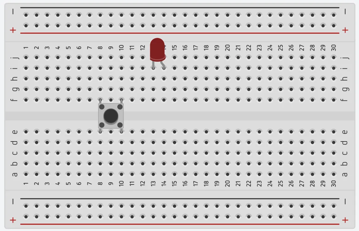 .
.
step 3: Take one resistor and connect one terminal of the resistor to the longer pin of the LED positive terminal (+) on the breadboard and the other pin of the resistor into the vertical connected wholes on the breadboard.
 .
.
Note: NB: This completes the circuit for the LED, allowing current to flow from the digital pin, through the LED and back to ground.
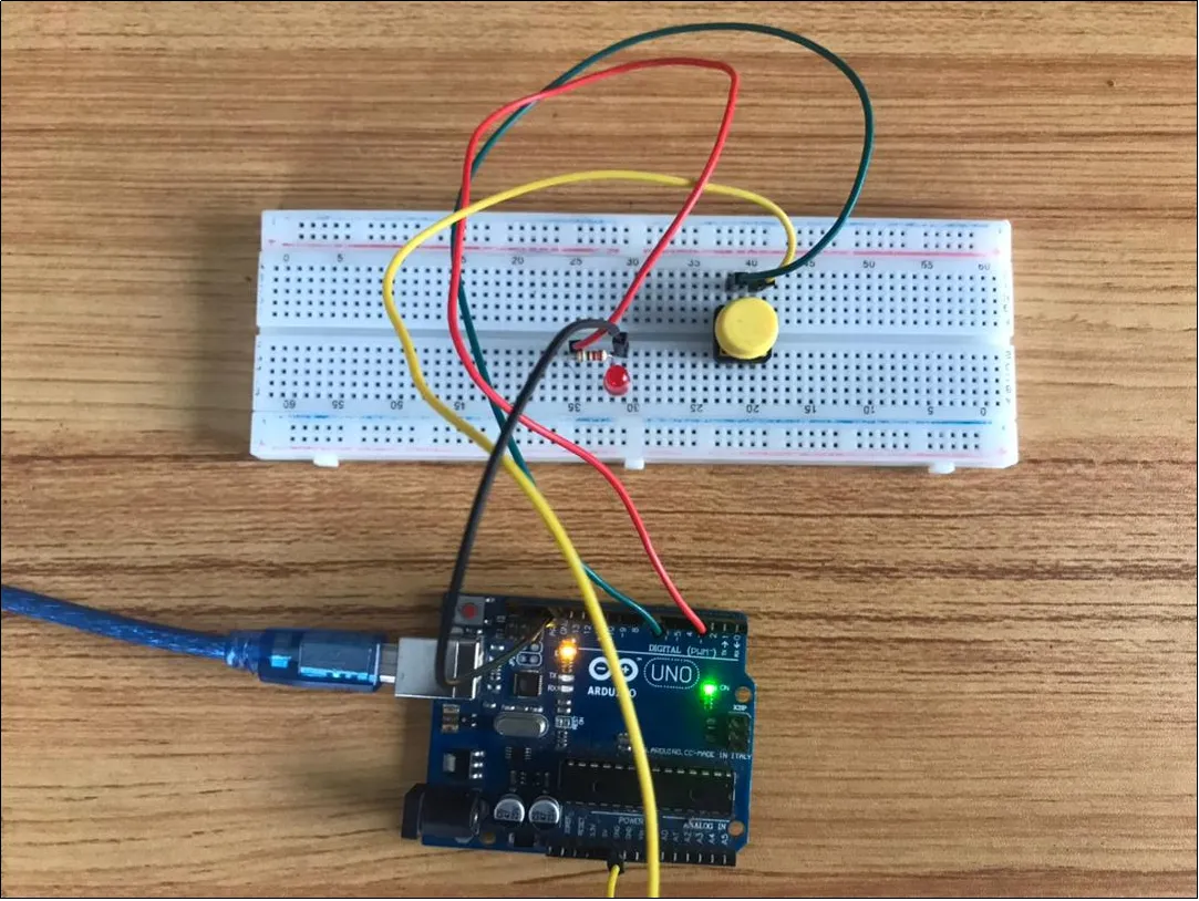
WIRING THE CIRCUIT
Things Needed:
- Blue jumper wire= 1
- Yellow jumper wire= 1
- Black jumper wire= 1
- Red jumper wire= 1
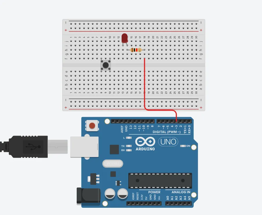
step 1: Connect red male-to-male jumper wire from the free end of the resistor to digital pin (13) on the Arduino UNO.
 .
.
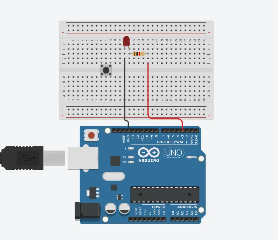
step 2: Connect Black male-to-male jumper wire from the free end of the LED negative pin power GND (Ground) on the Arduino UNO.
 .
.
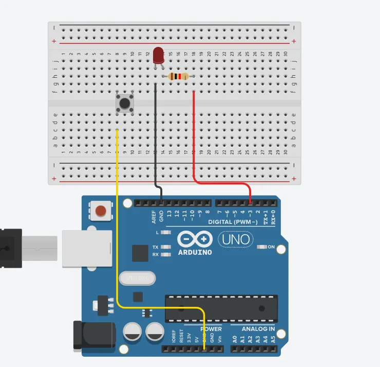
step 3: Connect Yellow male-to-male jumper wire from one Pin of the Push Button as a negative to power GND (Ground) on the Arduino UNO.
 .
.
step 4: Finally, connect blue male-to-male jumper wire from the other Pin of the push button (not connected to GND) to any digital pin on the Arduino UNO. Let's use digital pin 2 in this tutorial.
 .
.
PROGRAMMING
Step 1: Open your Arduino IDE. See how to set up here: Getting Started.
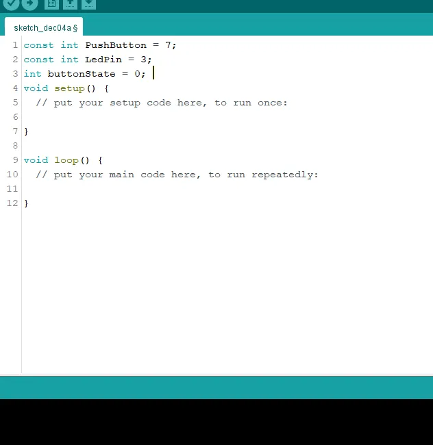
Step 2: Type the following codes before the void setup function.
 .
.
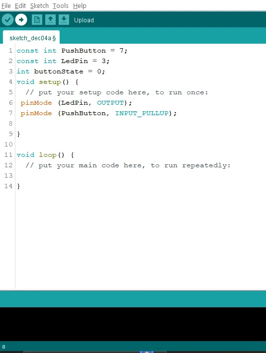
Step 3: After the void setup ()within the curly brackets type the following codes.
 .
.
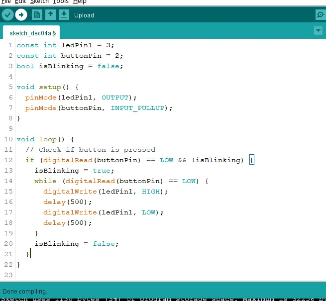
Step 4: : After the (void loop ()) within the curly brackets type
  if (digitalRead(buttonPin) == LOW && !isBlinking) {
    isBlinking = true;
    while (digitalRead(buttonPin) == LOW) {
      digitalWrite(ledPin1, HIGH);
      delay(500);
      digitalWrite(ledPin1, LOW);
      delay(500);
    }
    isBlinking = false;
  }
 .
.
Uploading the code
Step 1: Save your code. See the Getting Started section
Step 2: Select the arduino board and port See the Getting Started section:Selecting Arduino Board Type and Uploading your code.
Step 3: Upload your code. See the Getting Started section:Selecting Arduino Board Type and Uploading your code
OBSERVATION
 .
.
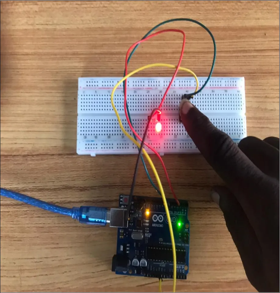 .
.