Project 2.5.5:LED Control with Arduino and Push Button
| Description | You will learn how to create a simple circuit using an Arduino microcontroller and a push button to make two LED blink. | | --------------- | -------------------------------------------------------------------------------------------------------------------------------------------------------------------------------------------------------------- | | Use case | The use case for using a push button to control the blinking of LEDs is to provide customizable visual feedback, signaling/alerting functionality, interactive lighting, educational demonstrations, or prototyping/testing capabilities. |
Components (Things You will need)
 |
 |
 |
 |
 |
 |
|---|---|---|---|---|---|
Building the circuit
Things Needed:
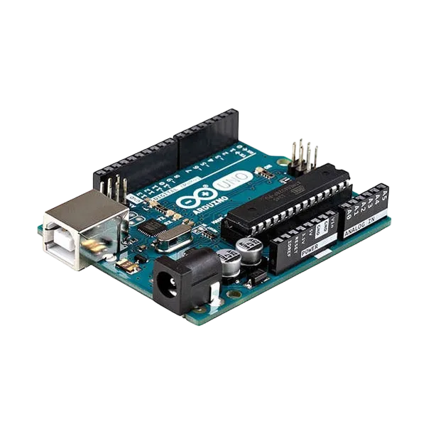
- Arduino Uno = 1
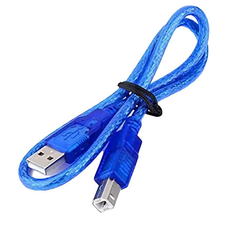
- Arduino USB cable = 1
- Resistor = 1
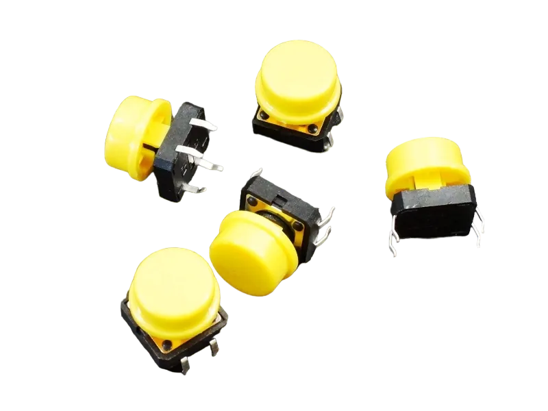
- Push button = 1
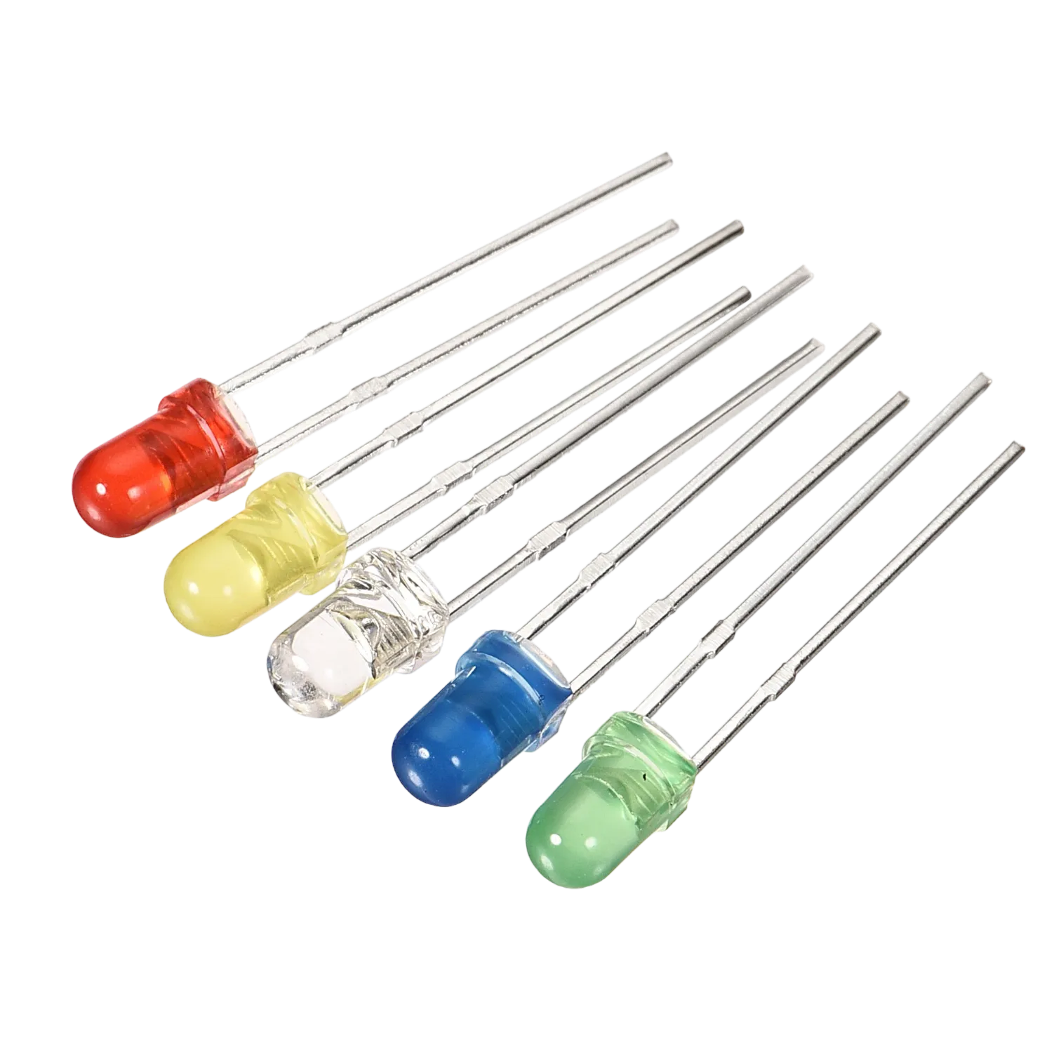
- Red LED = 1
- Yellow LED = 1
- Green LED = 1
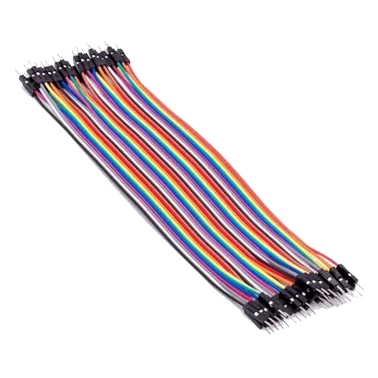
- Blue jumper wire= 1
- Yellow jumper wire= 1
- Black jumper wire= 1
- Red jumper wire= 1
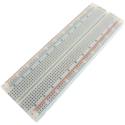
Mounting the component on the breadboard
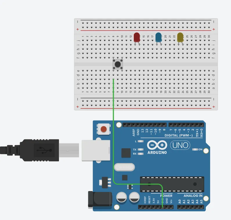
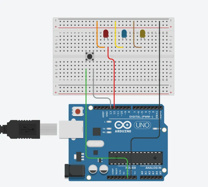
Step 1: Connect the push button on the breadboard but make sure the two pair of the pins are connected on each side of the bridge.
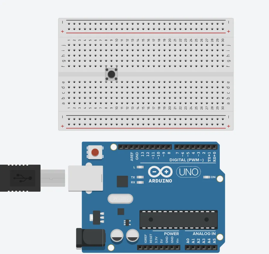 .
.
step 2: Inset three (3) LEDs on the breadboard as shown in the picture below.
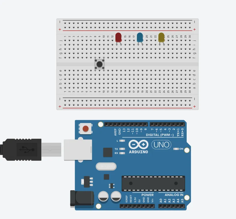 .
.
WIRING THE CIRCUIT
Things Needed:
- Blue jumper wire= 1
- Yellow jumper wire= 1
- Black jumper wire= 1
- Red jumper wire= 1
- White jumper wire= 1
- Green jumper wire= 1
step 1: Connect the green male-to-male jumper wire from one Pin of the Push Button as a negative to power GND (Ground) on the Arduino UNO.
 .
.
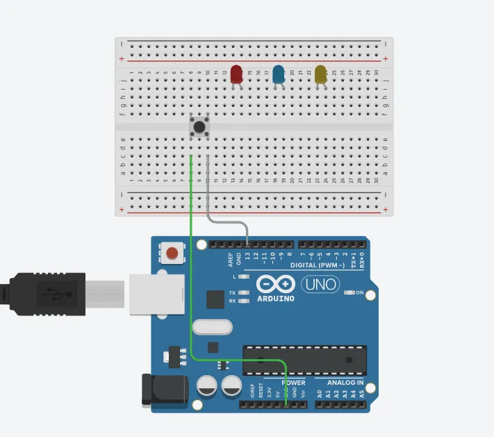
step 2: Connect the white male-to-male jumper wire from the other Pin of the push button (not connected to GND) to a digital pin 13 on the Arduino UNO.
 .
.
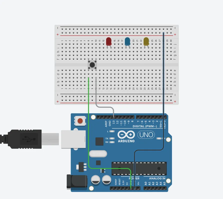
step 3: Connect the blue male-to-male jumper wire from the Arduino GND to the negative holes on the breadboard.
 .
.
step 4: Connect three male-to-male jumper wires from the each of the LEDs negative pin to the negative holes on the breadboard.
 .
.
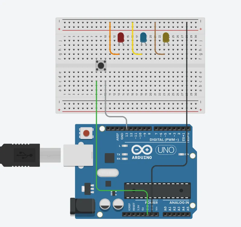
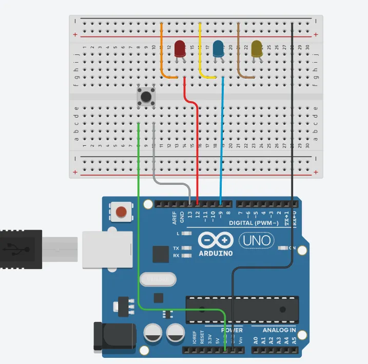
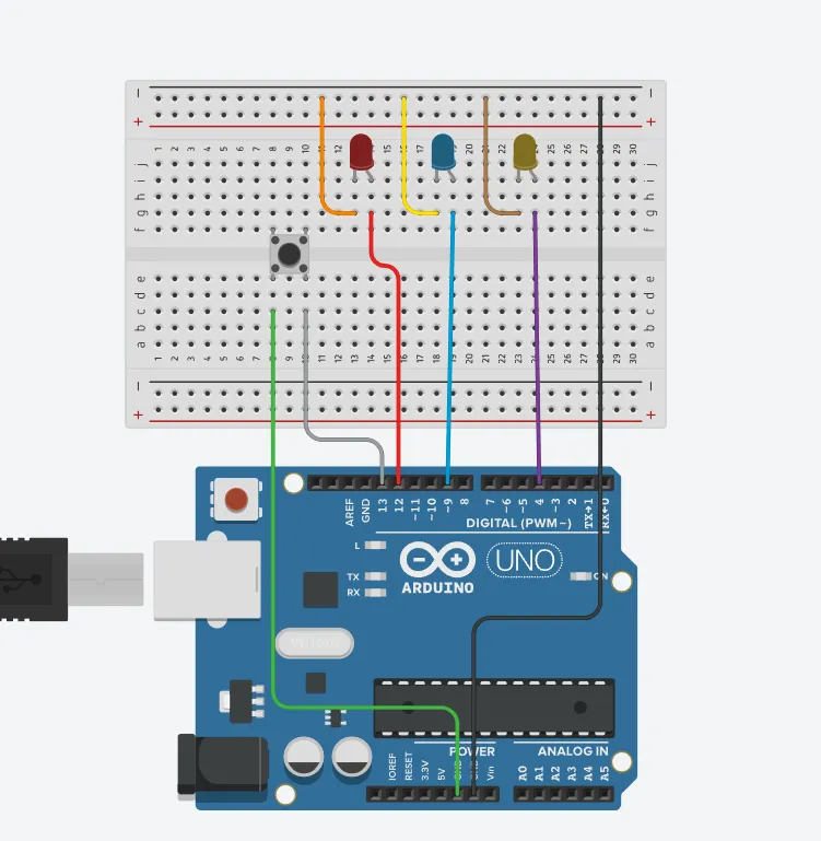
step 5: Connect a red male-to-male jumper wire from the longer pin of the first LED as a positive to digital pin 12 on the Arduino UNO.
 .
.
step 6:Connect a see blue male-to-male jumper wire from the longer pin of the second LED as a positive to digital pin 9 on the Arduino UNO.
 .
.
step 7: Connect a violet male-to-male jumper wire from the longer pin of the third LED as a positive to digital pin 4 on the Arduino UNO.
 .
.
PROGRAMMING
Step 1: Open your Arduino IDE. See how to set up here: Getting Started.
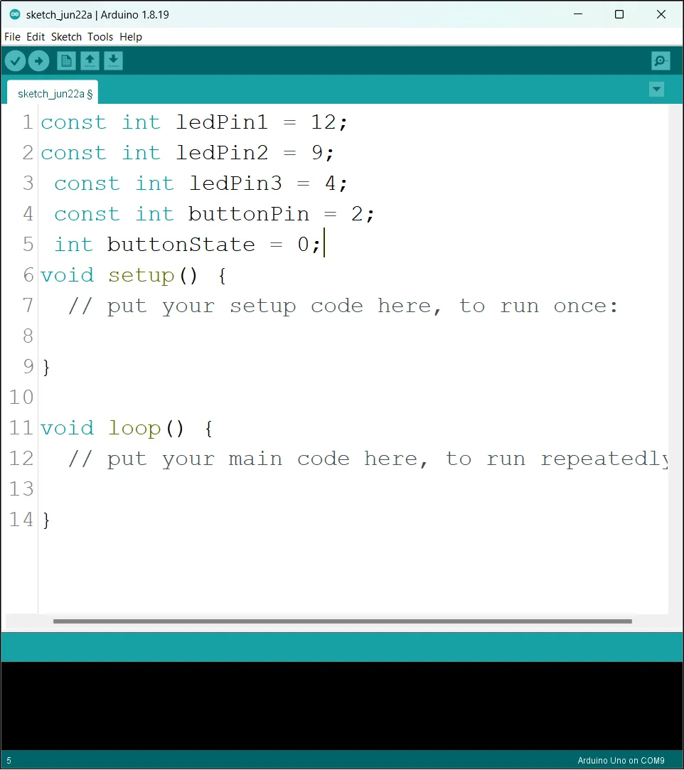
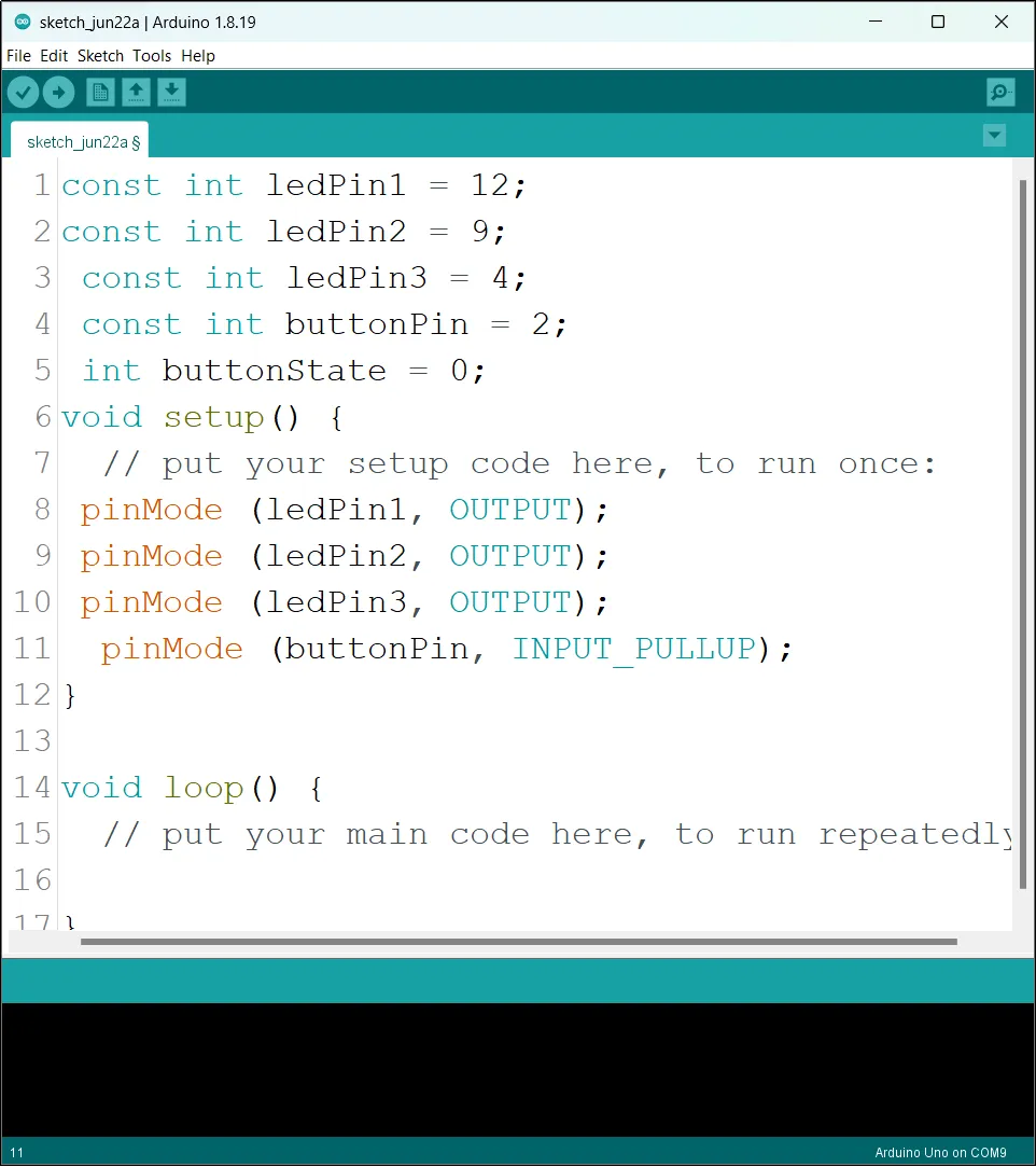
Step 2: Type the following codes before the void setup function.
const int ledPin1 = 12;
const int ledPin2 = 9;
const int ledPin3 = 4;
const int buttonPin = 2;
int buttonState = 0;
 .
.
Step 3: After the void setup ()within the curly brackets type the following codes.
pinMode (ledPin1, OUTPUT);
pinMode (ledPin2, OUTPUT);
pinMode (ledPin3, OUTPUT);
pinMode (buttonPin, INPUT_PULLUP);
 .
.
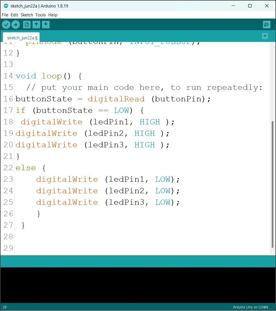
Step 4: : After the (void loop ()) within the curly brackets type
 buttonState = digitalRead (buttonPin);
  if (buttonState == LOW) {
 digitalWrite (ledPin1, HIGH );
digitalWrite (ledPin2, HIGH );
digitalWrite (ledPin3, HIGH );
}
 else {
    digitalWrite (ledPin1, LOW);
    digitalWrite (ledPin2, LOW);
    digitalWrite (ledPin3, LOW);
    }
 .
.
Uploading the code
Step 1: Save your code. See the Getting Started section
Step 2: Select the arduino board and port See the Getting Started section:Selecting Arduino Board Type and Uploading your code.
Step 3: Upload your code. See the Getting Started section:Selecting Arduino Board Type and Uploading your code
CONCLUSION
If you encounter any problems when trying to upload your code to the board, run through your code again to check for any errors or missing lines of code. If you did not encounter any problems and the program ran as expected, Congratulations on a job well done.