Project 2.7.1:Push Button with Traffic Light Module
| Description | You will learn how to create a simple circuit using an Ultrasonic distance sensor and the buzzer. |
|---|---|
| Use case | Imagine you want to program a pedestrian traffic light to allow pedestrians to cross the street at the push of a button. |
Components (Things You will need)
 |
 |
 |
 |
 |
 |
|---|---|---|---|---|---|
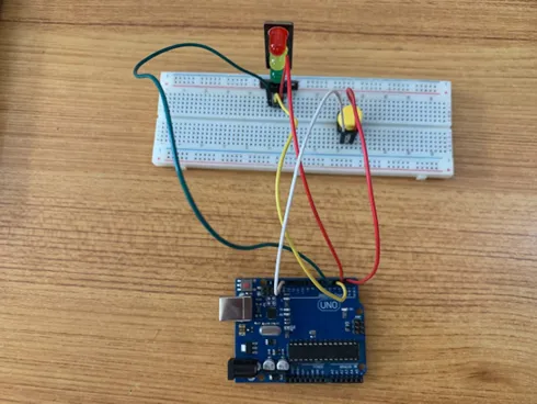
Building the circuit
Things Needed:
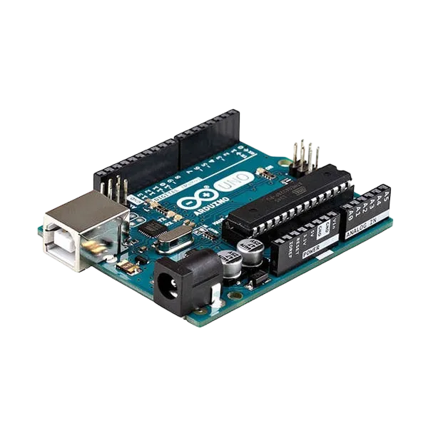
- Arduino Uno = 1
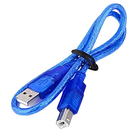
- Arduino USB cable = 1
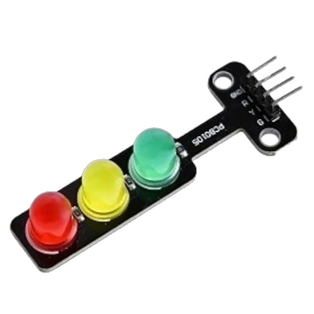
- Traffic Light= 1
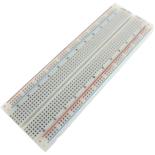
- Breadboard = 1
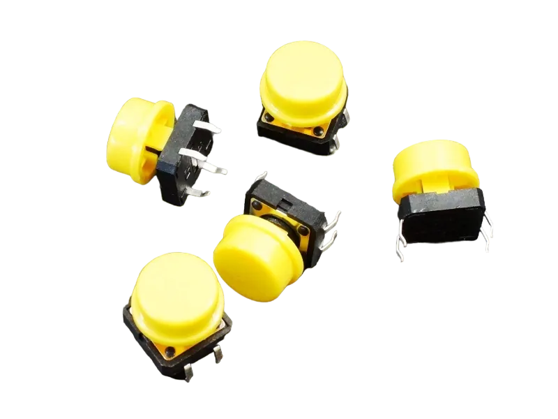
- Pushbutton = 1
Mounting the component on the breadboard
Things Needed:
- Traffic Light Module = 1
- Push Button = 1
- Breadboard = 1
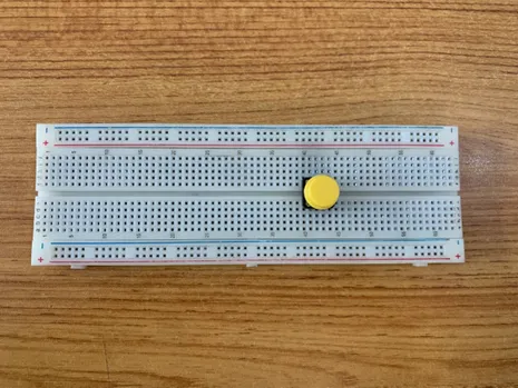
Step 1: - The push button has four unassigned pins. - On the middle section of the breadboard, locate each horizontal section lettered A to J. - Take the push button and insert two pins into the lettered section ‘g’ horizontally. - Insert the other two pins into the lettered section ‘d’ horizontally.
 .
.
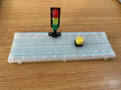
Step 2: - The Traffic light module has four pins (Red(R), Yellow(Y)), Green(G) and GND. - On the middle section of the breadboard, locate each horizontal section lettered A to J. - Take the RGB module and insert it into any of the lettered section (Say A) horizontally.
 .
.
WIRING THE CIRCUIT
Things Needed:
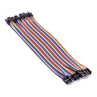
- Red male-male-to-male jumper wires = 2
- White male-to-male jumper wires = 2
- Green male-to-male jumper wires = 2
- Yellow male-to-male jumper wires = 2
- Arduino Uno Board
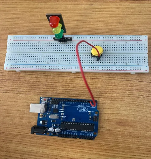
Step 3: Take the Red male-male-to-male jumper wire and place one side of the wire pin under the push button pin located on the lettered section ‘d’ and the other side of the wire pin to the digital pin 2 on the Arduino uno board. .
Step 4: Take the White male-male-to-male jumper wire and place one side of the wire pin under the other pin located on the lettered section ‘d’ and the other side of the wire pin to GND on the Arduino uno board.
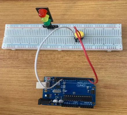 .
.
Step 5: Take the Red male-to-male jumper wire and place one side of the wire pin under the Red pin of the traffic light module and the other side of the wire pin to the digital pin 3 on the Arduino uno board.
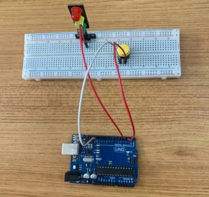 .
.
Step 6: Take the Yellow male-to-male jumper wire and place one side of the wire pin under the yellow pin of the traffic light module and the other side of the wire pin to the digital pin 5 on the Arduino uno board.
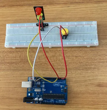 .
.
Step 7: Take the Green male-to-male jumper wire and place one side of the wire pin under the Green pin of the traffic light module and the other side of the wire pin to the digital pin 4 on the Arduino uno board.
 .
.
Step 8: Finally, Take the White male-male-to-male jumper wire and place one side of the wire pin under the GND pin of the module and the other side of the wire pin to the GND port on the Arduino Uno Board.
 .
.
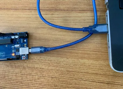
Connecting The Arduino Uno Board To Your Laptop.
Arduino Uno Board Arduino cable
Step 7: Connect the USB port of the Arduino cable to the USB port of your laptop and the other side to the Arduino Uno Board.
 .
.
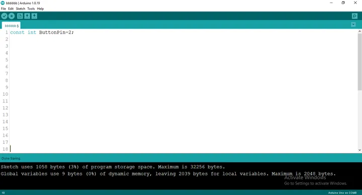
PROGRAMMING
Step 1: Open your Arduino IDE. See how to set up here: Getting Started.
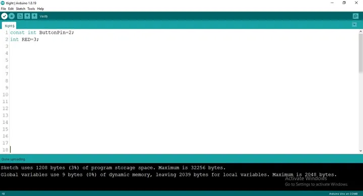
Step 2: Type const int Button = 2; as shown in the picture below.
 .
.
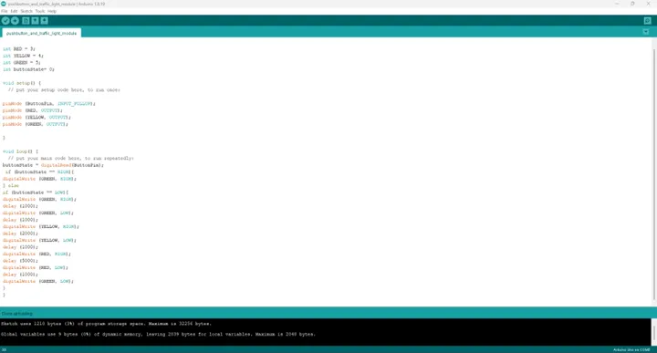
Step 3: Type int RED = 3; as shown in the picture below.
 .
.
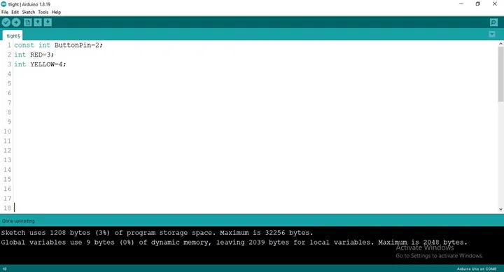
Step 4: Type int YELLOW = 3; as shown in the picture below.
 .
.
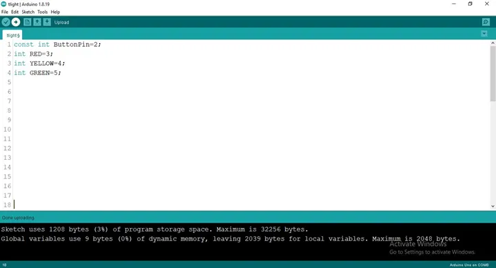
Step 5: Type int GREEN = 3; as shown in the picture below.
 .
.
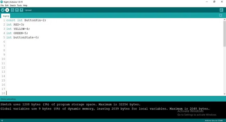
Step 6: Type int buttonState= 0; as shown in the picture below.
 .
.
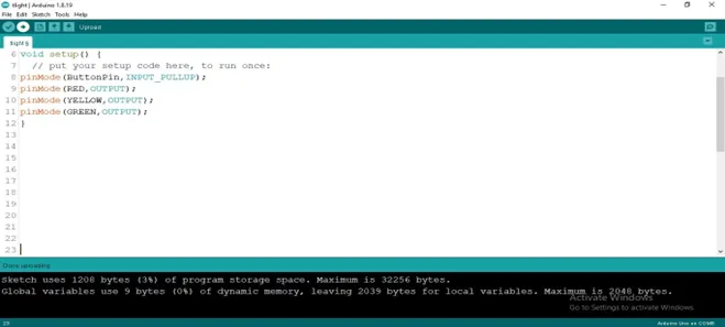
Step 7: After the (void setup ()) within the curly brackets type
pinMode (ButtonPin, INTPUT_PULLUP);
pinMode (RED, OUTPUT);
pinMode (YELLOW, OUTPUT);
pinMode (GREEN, OUTPUT);
 .
.
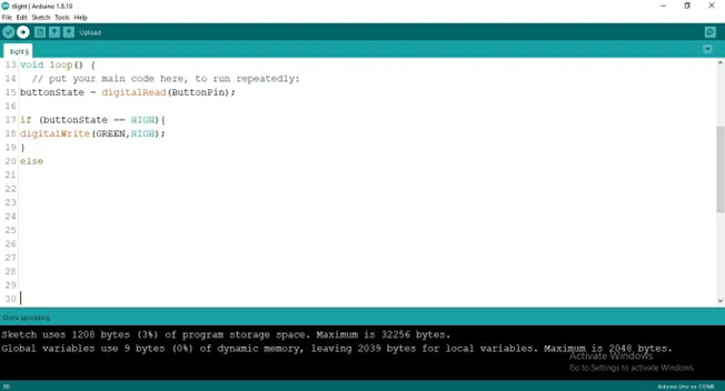
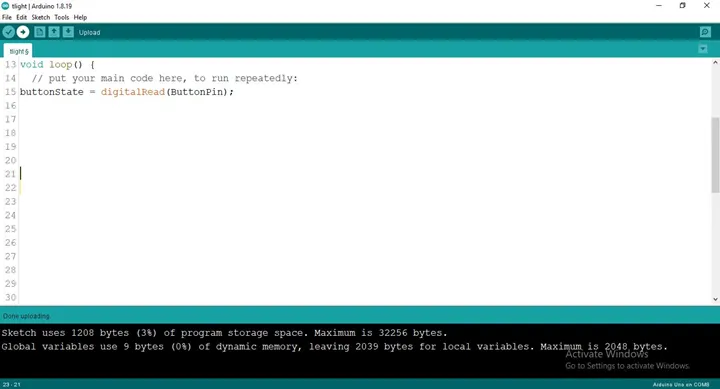
Step 8: After the (void loop ()) within the curly brackets type as shown below
 .
.
Step 9: Type Function
.
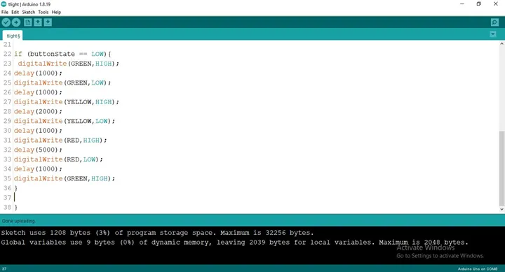
Step 10: Type Function
if (buttonState == LOW) {
digitalWrite (GREEN, HIGH);
delay (1000);
digitalWrite (GREEN, LOW);
delay (1000);
digitalWrite (YELLOW, HIGH);
delay (2000);
digitalWrite (YELLOW, LOW);
delay (1000);
digitalWrite (RED, LOW);
delay (5000);
digitalWrite (RED, LOW);
delay (1000);
digitalWrite (GREEN, LOW);
}
 .
.
 .
.
Step 11: Save your code. See the Getting Started section
Step 12: Select the arduino board and port See the Getting Started section:Selecting Arduino Board Type and Uploading your code.
Step 13: Upload your code. See the Getting Started section:Selecting Arduino Board Type and Uploading your code
CONCLUSION
If you encounter any problems when trying to upload your code to the board, run through your code again to check for any errors or missing lines of code. If you did not encounter any problems and the program ran as expected, Congratulations on a job well done.