Project 3.2.1: SMART SECURITY SYSTEM
| Description | This smart security system uses an ultrasonic sensor to detect objects within a specified range. When an object is detected, a red LED lights up, and a buzzer sounds to alert users. |
|---|---|
| Use case | Ideal for securing entry points, monitoring restricted areas, or alerting when someone enters a protected zone.. |
Components (Things You will need)
 |
 |
 |
 |
 |
 |
 |
|---|---|---|---|---|---|---|
Building the circuit
Things Needed:
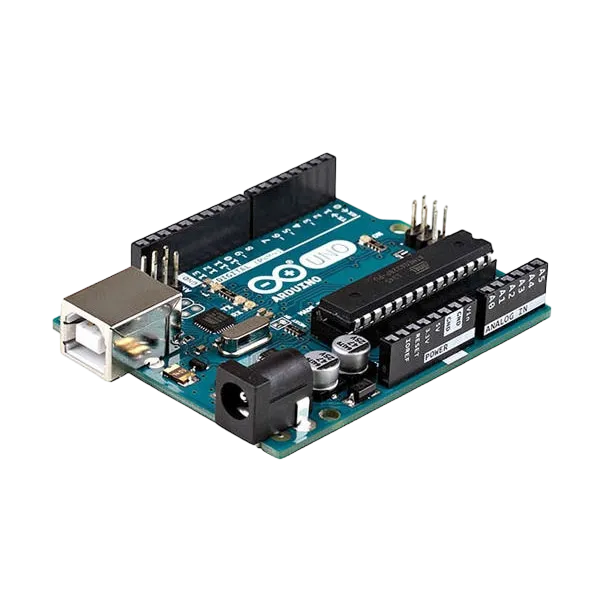
- Arduino Uno = 1
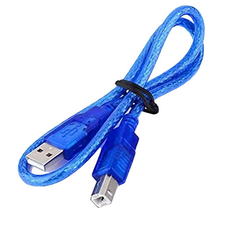
- Arduino USB cable = 1
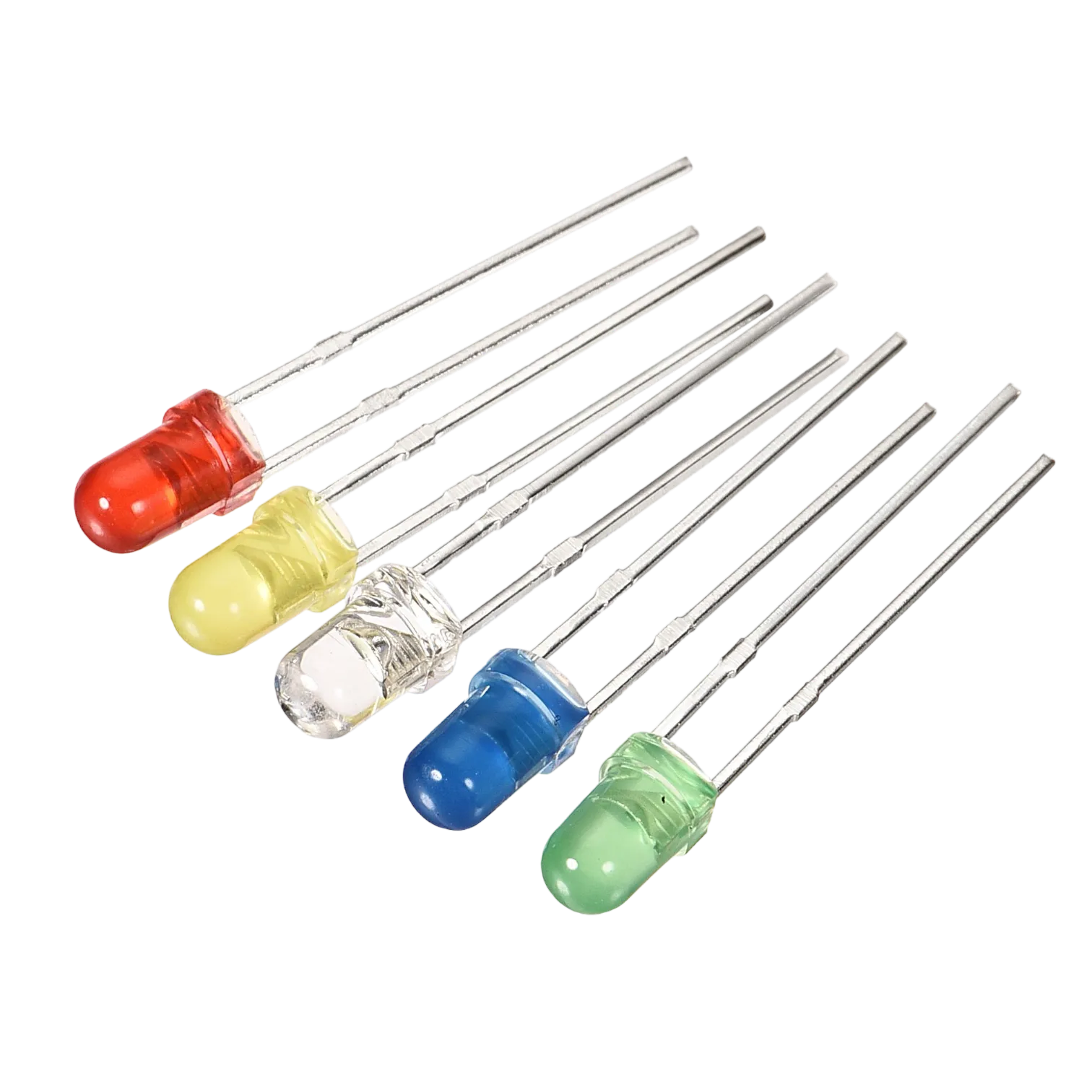
- Red LED = 1
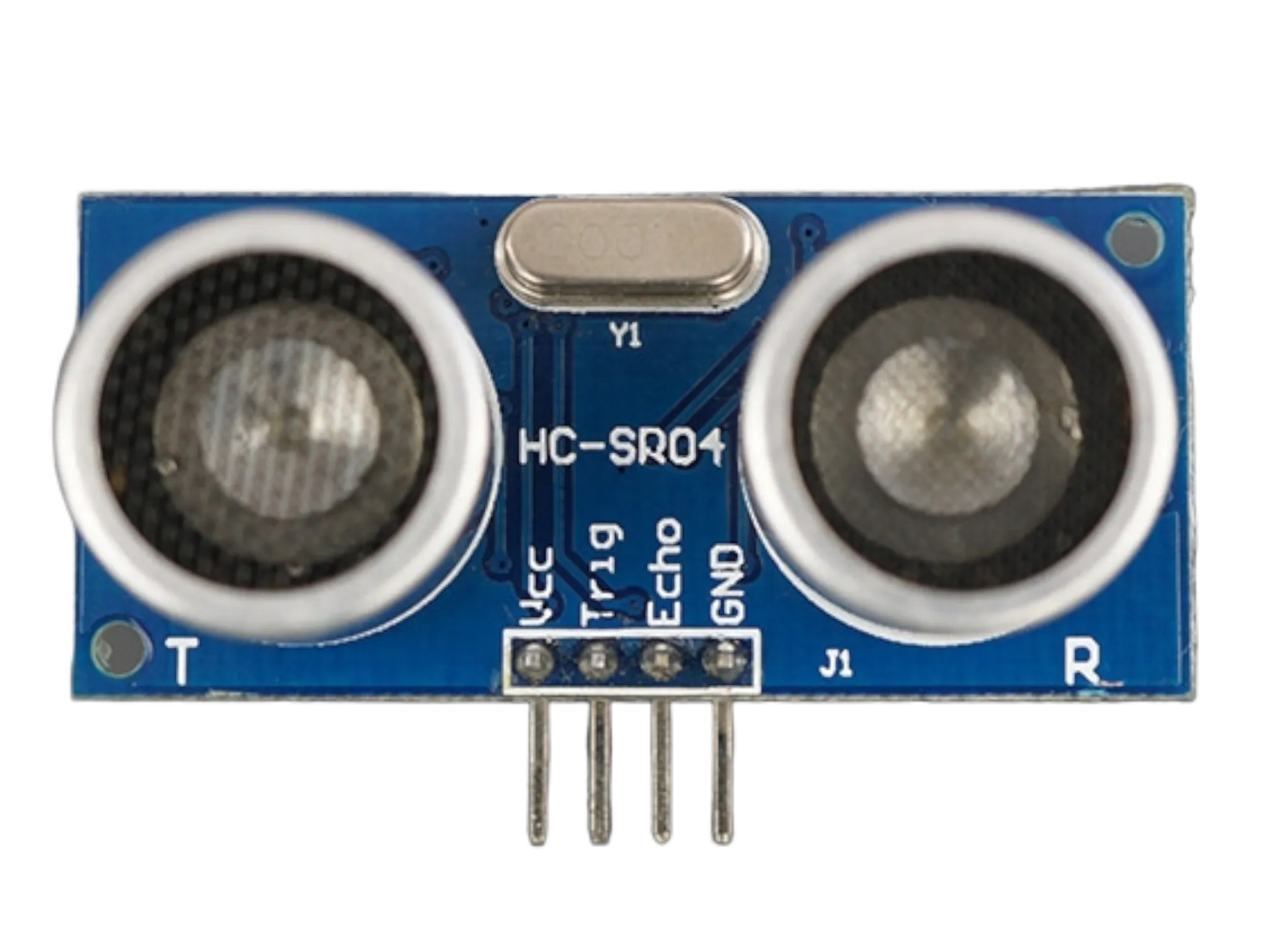
- Ultrasonic sensor = 1
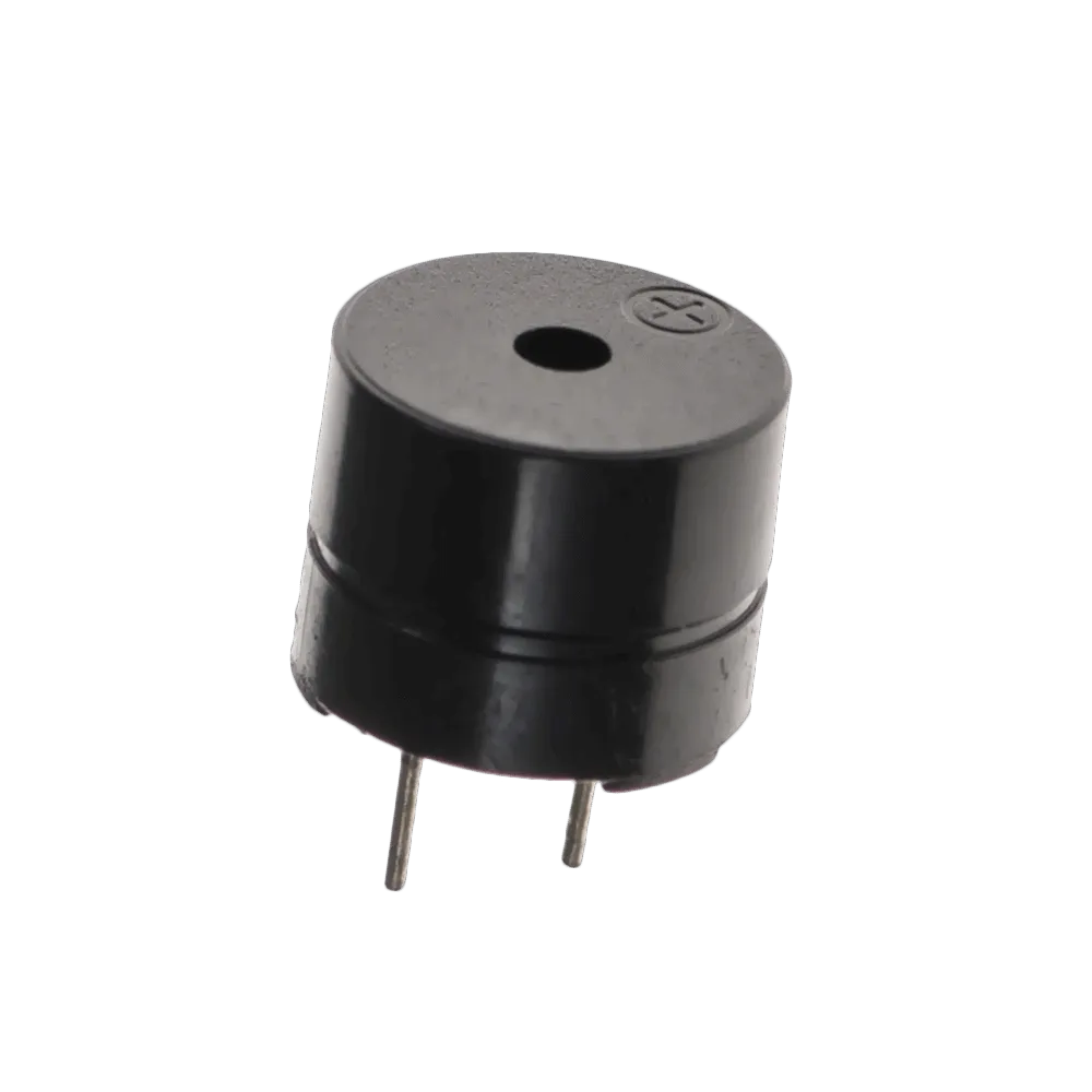
- Buzzer = 1
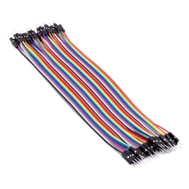
- Red jumper wire = 1
- Blue jumper wire = 1
- Black jumper wires = 2
- White jumper wire = 1
- Orange jumper wire = 1
- Green jumper wire = 1
- Brown jumper wire =1
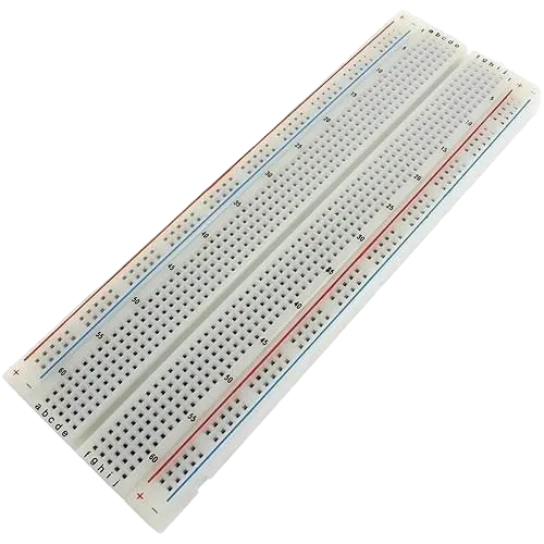
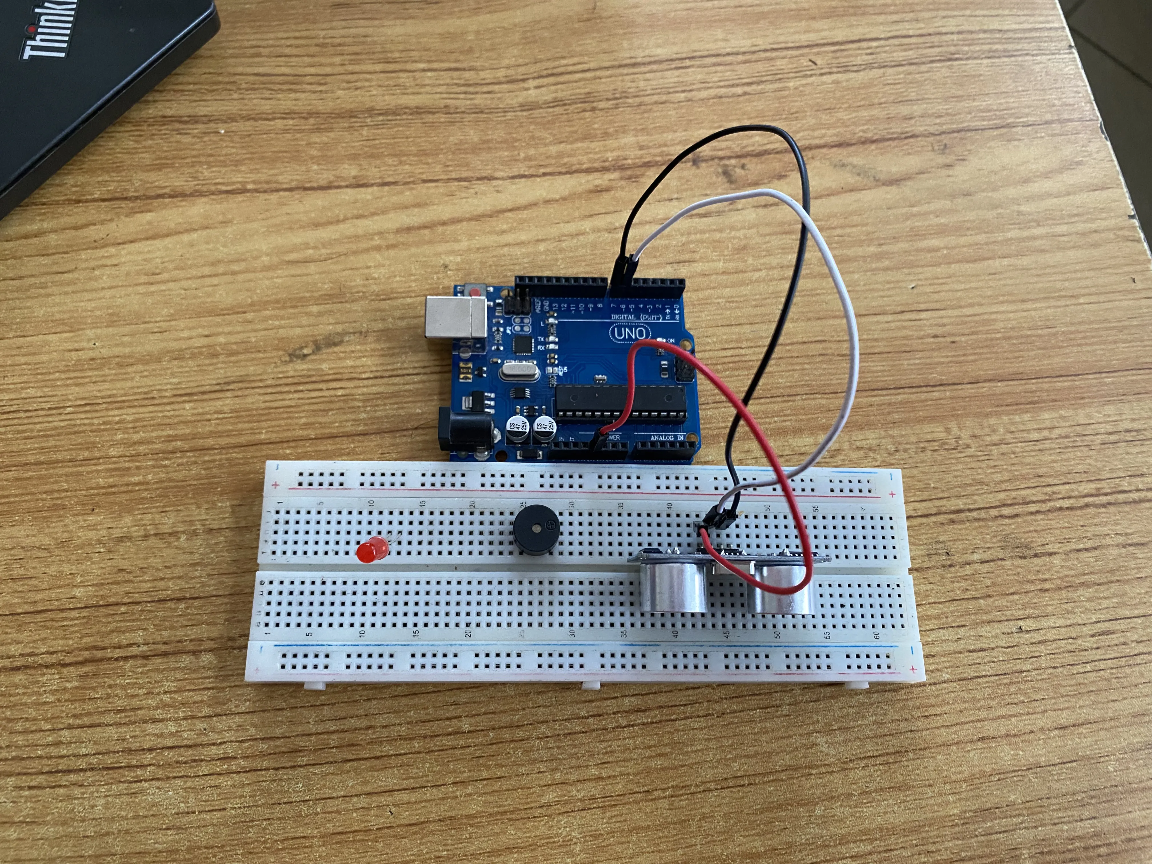
Mounting the component on the breadboard
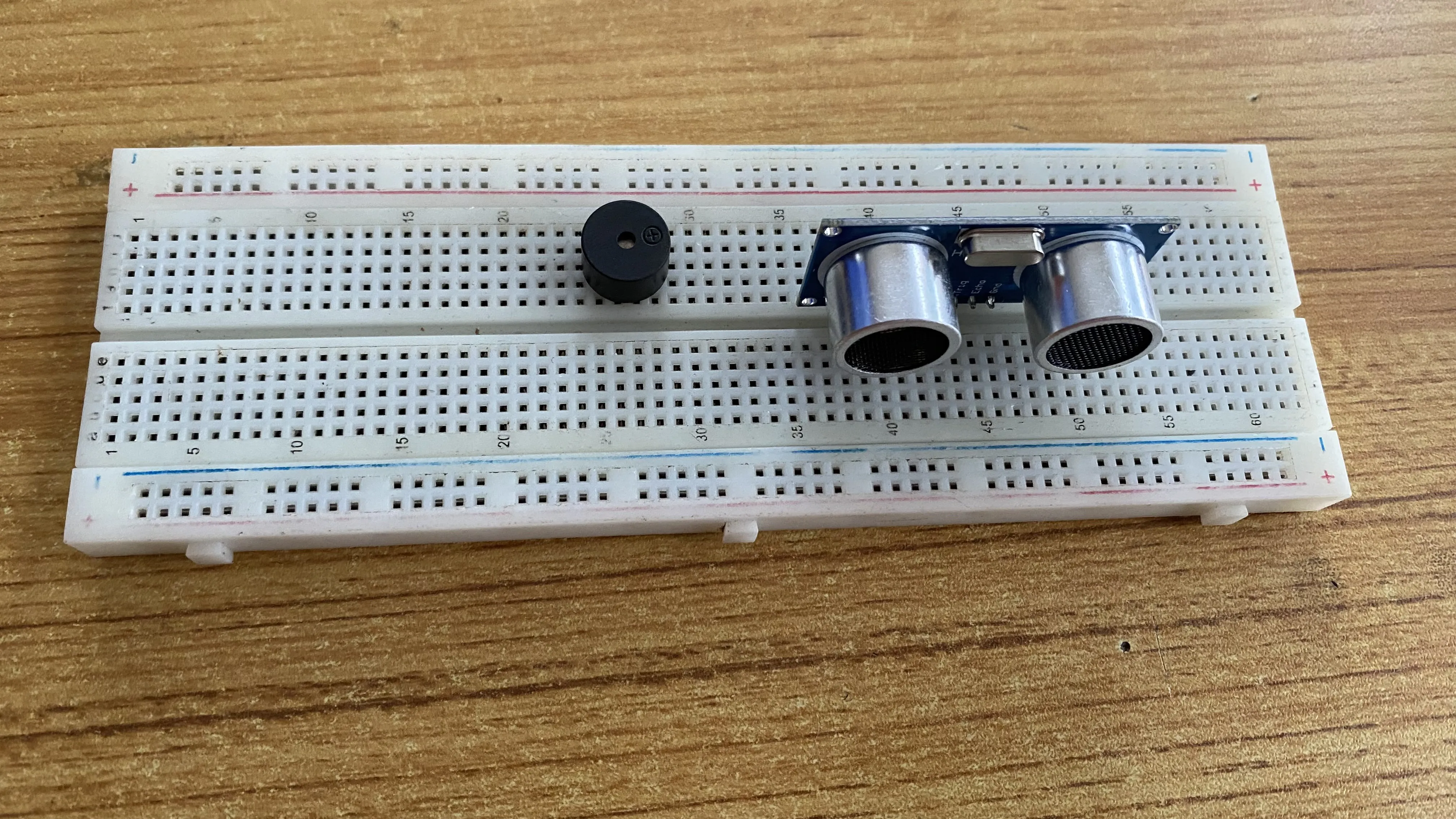
Step 1: Take the breadboard, the Ultrasonic sensor and insert it into the vertical connectors on the breadboard as shown below.
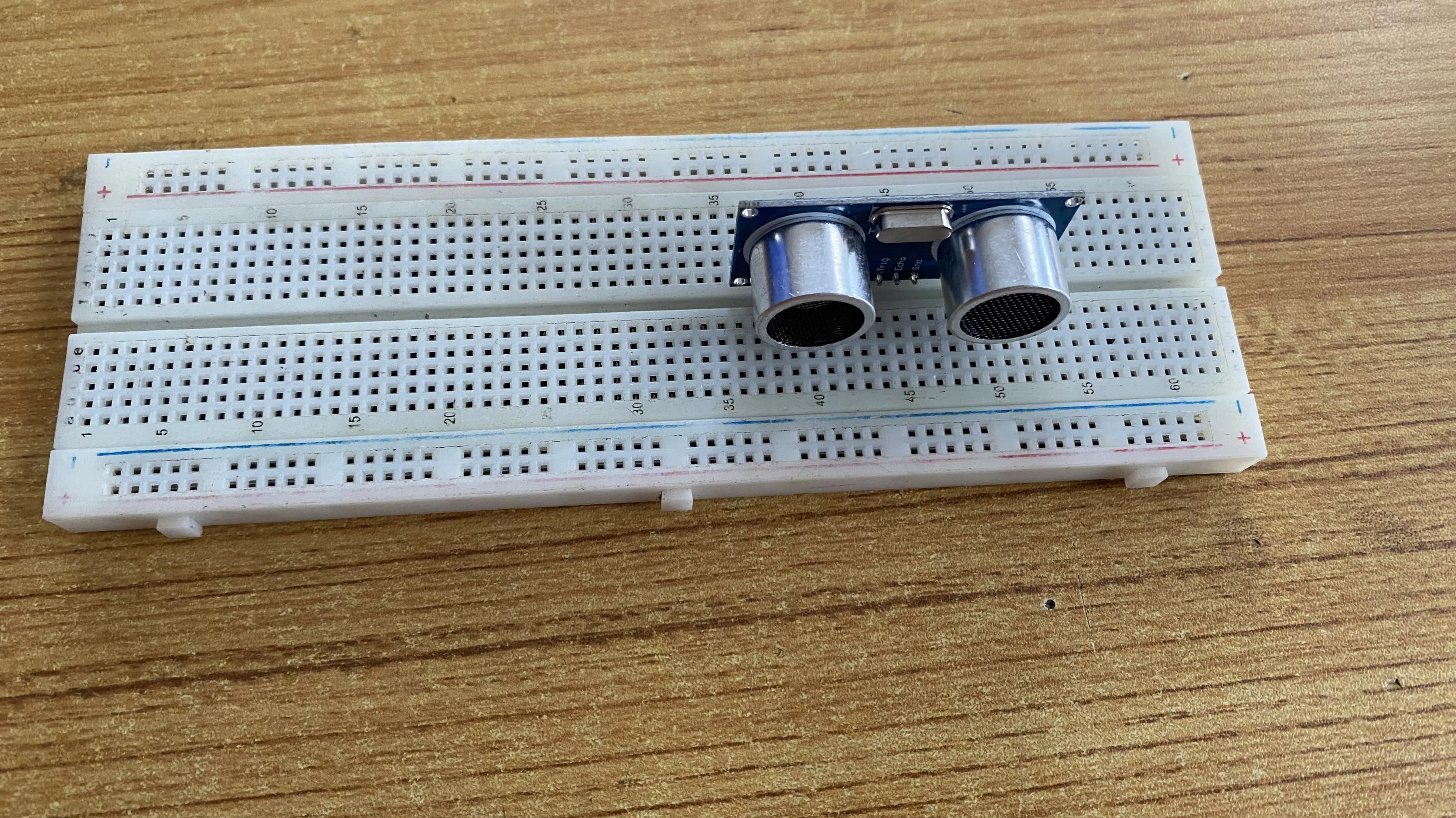 .
.
Step 2: Take the Buzzer and insert it into the vertical connectors on the breadboard beside the Ultrasonic sensor as shown below.
 .
.
Step 3: Take the red LED and insert it into the vertical connectors on the breadboard beside the buzzer as shown below.
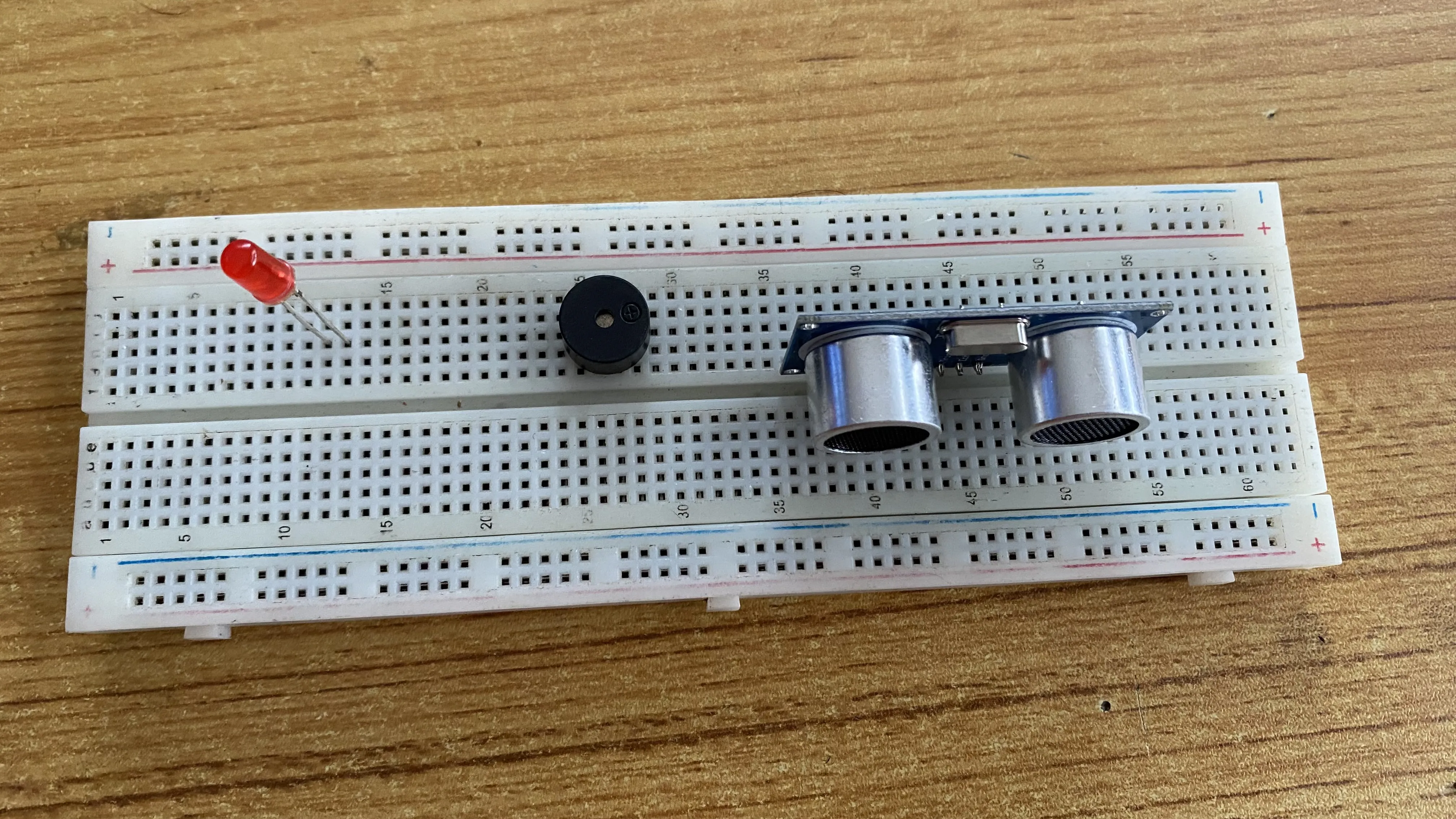 .
.
NB: Make sure you identify where the positive pin (+) and the negative pin (-) is connected to on the breadboard. The longer pin of the LED is the positive pin and the shorter one, the negative PIN.
WIRING THE CIRCUIT
Things Needed:
- Red jumper wire = 1
- Blue jumper wire = 1
- Black jumper wires = 2
- White jumper wire = 1
- Orange jumper wire = 1
- Green jumper wire = 1
- Brown jumper wire =1
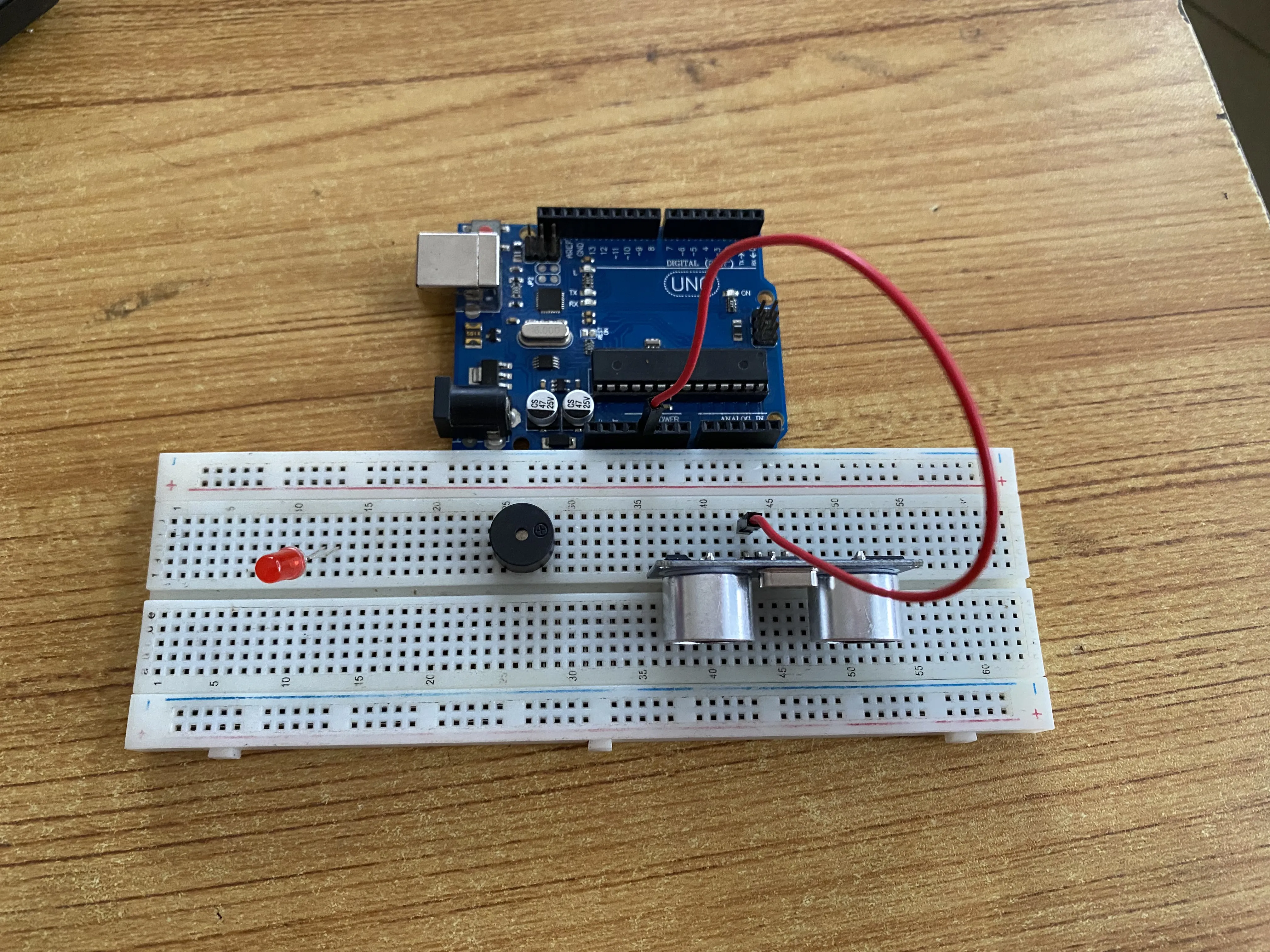
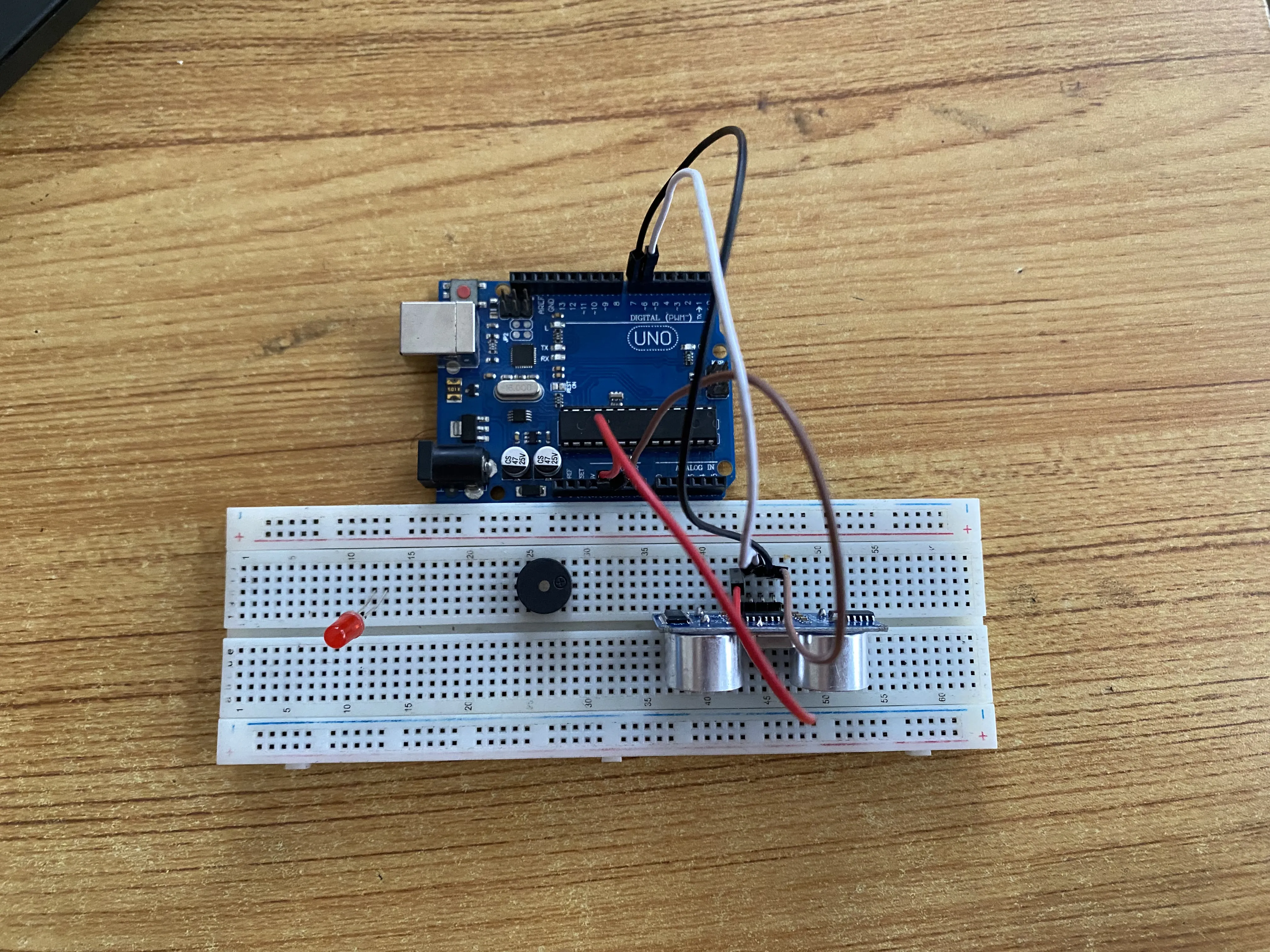
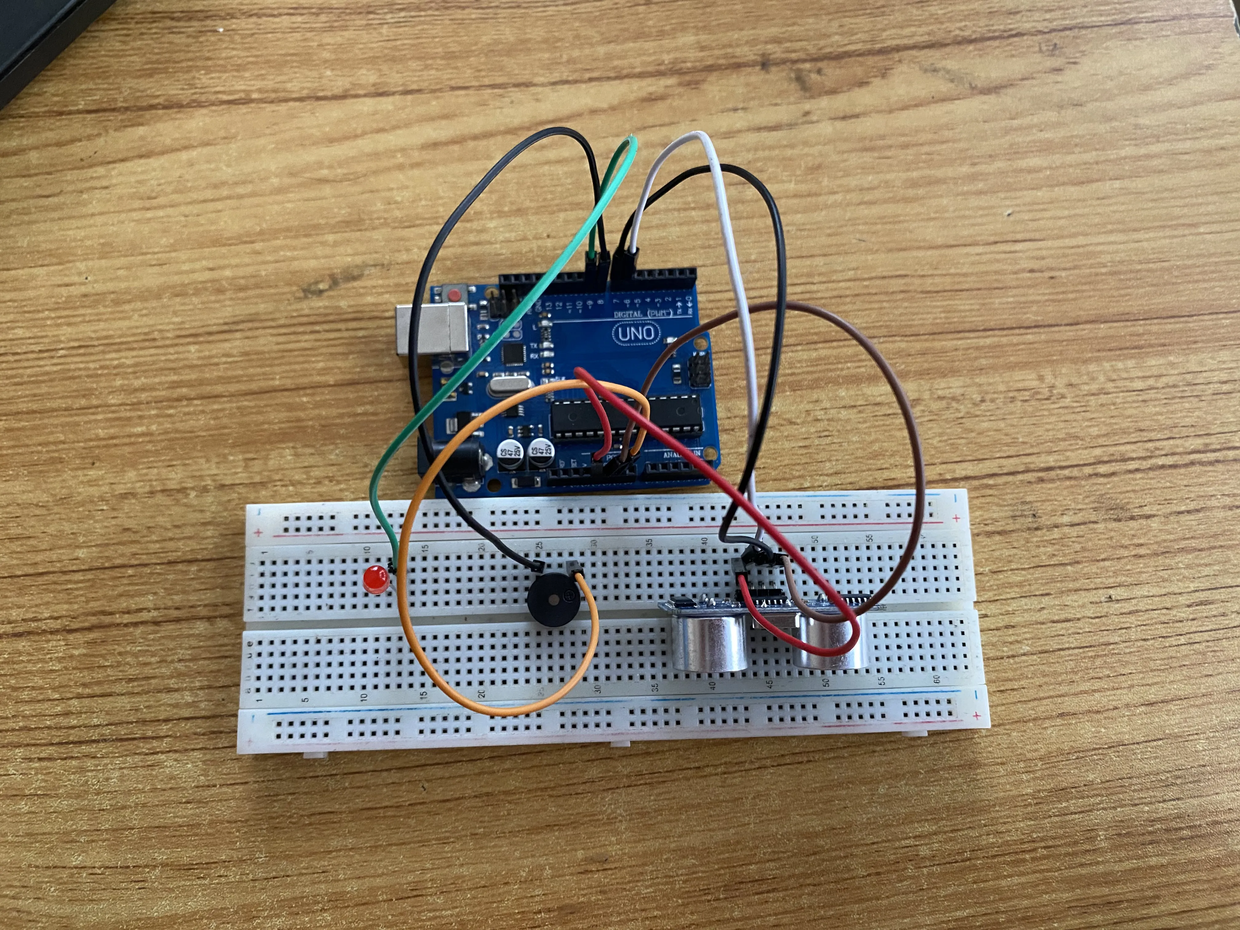
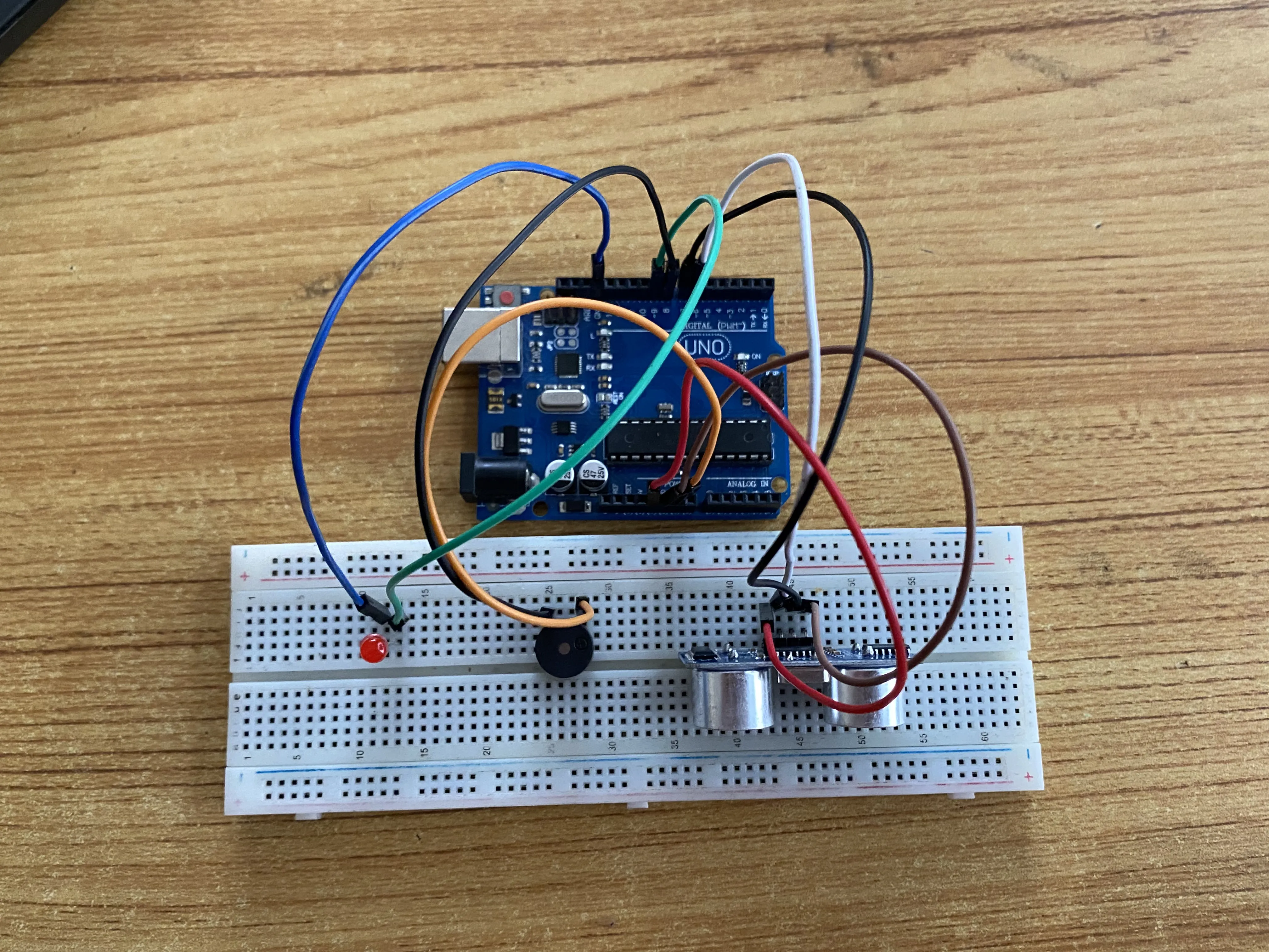
Step 1: Connect one end of red male-to-male jumper wire to the VCC pin of the ultrasonic sensor on the breadboard and the other end to 5v on the Arduino UNO as shown below.
Step 2: Connect one end of white male-to-male jumper wire to the TRIG pin of the ultrasonic sensor on the breadboard and the other end to digital pin number 6 on the Arduino UNO as shown below.
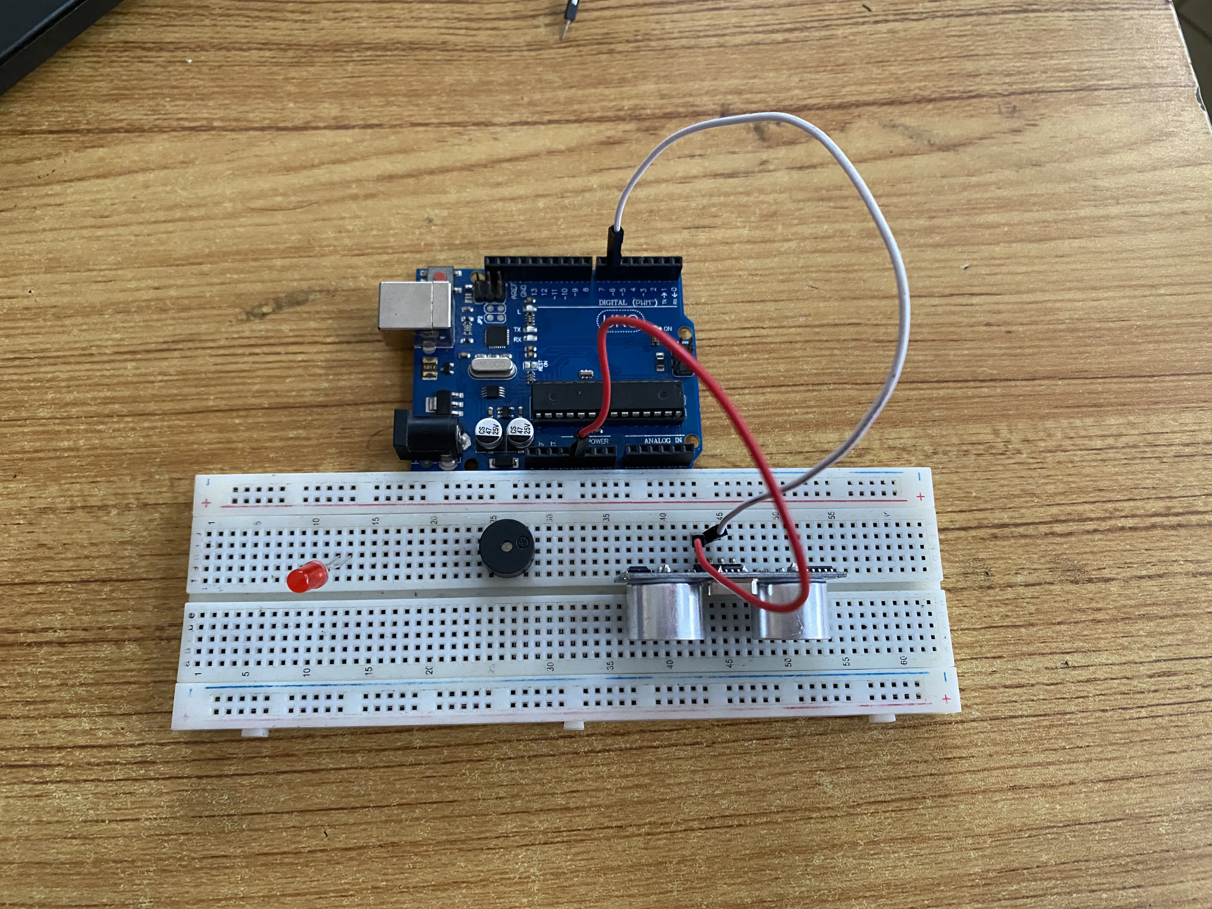 .
.
Step 3: Connect one end of black male-to-male jumper wire to the ECHO pin of the ultrasonic sensor on the breadboard and the other end to digital pin number 7 on the Arduino UNO as shown below.
Step 4:Connect one end of brown male-to-male jumper wire to the GND pin of the ultrasonic sensor on the breadboard and the other end to GND on the Arduino UNO as shown below.
 .
.
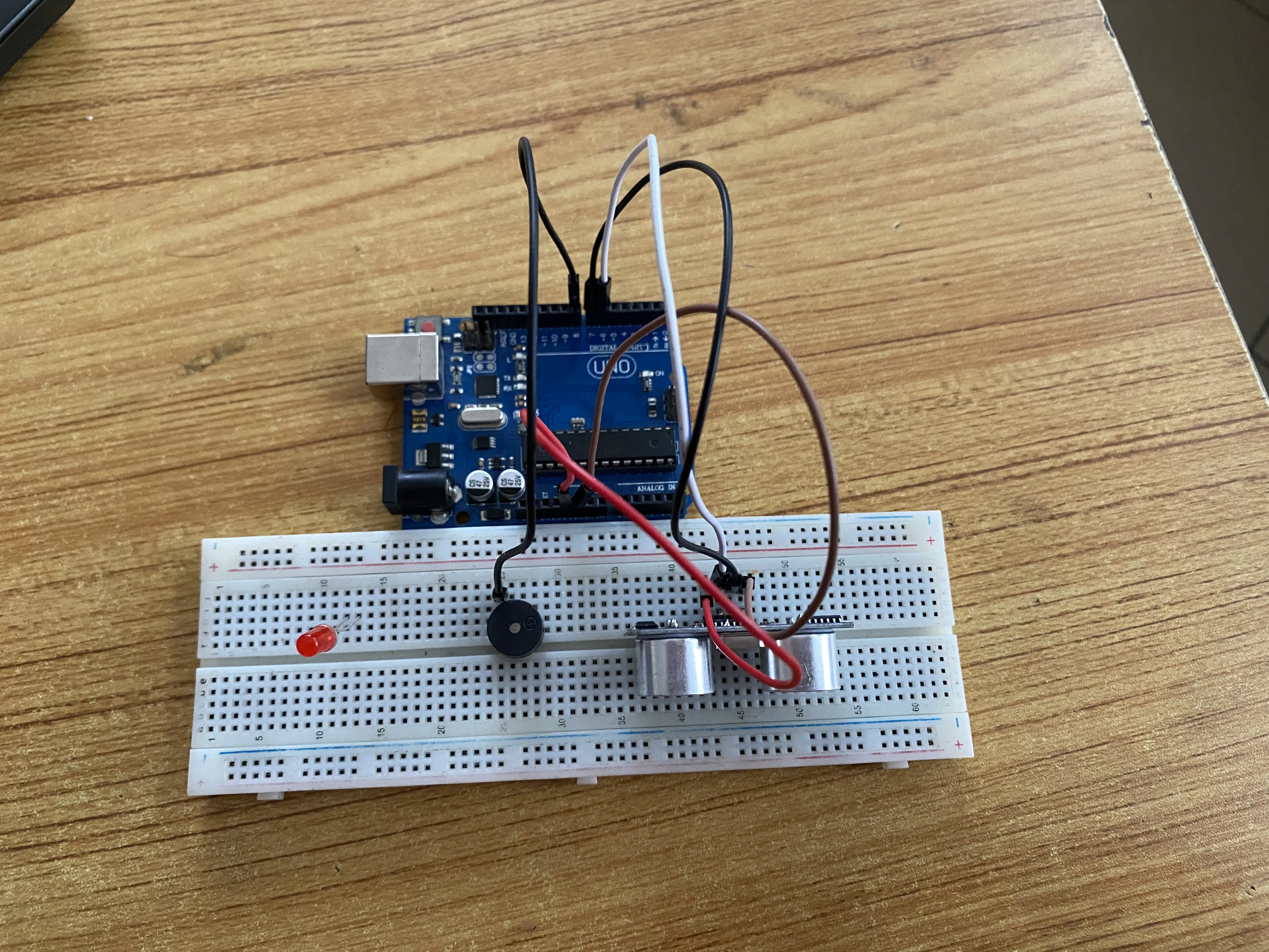
Step 5: Connect one end of the black male-to-male jumper wire to the positive pin of the buzzer on the breadboard to digital pin number 8 on the Arduino UNO as shown below
 .
.
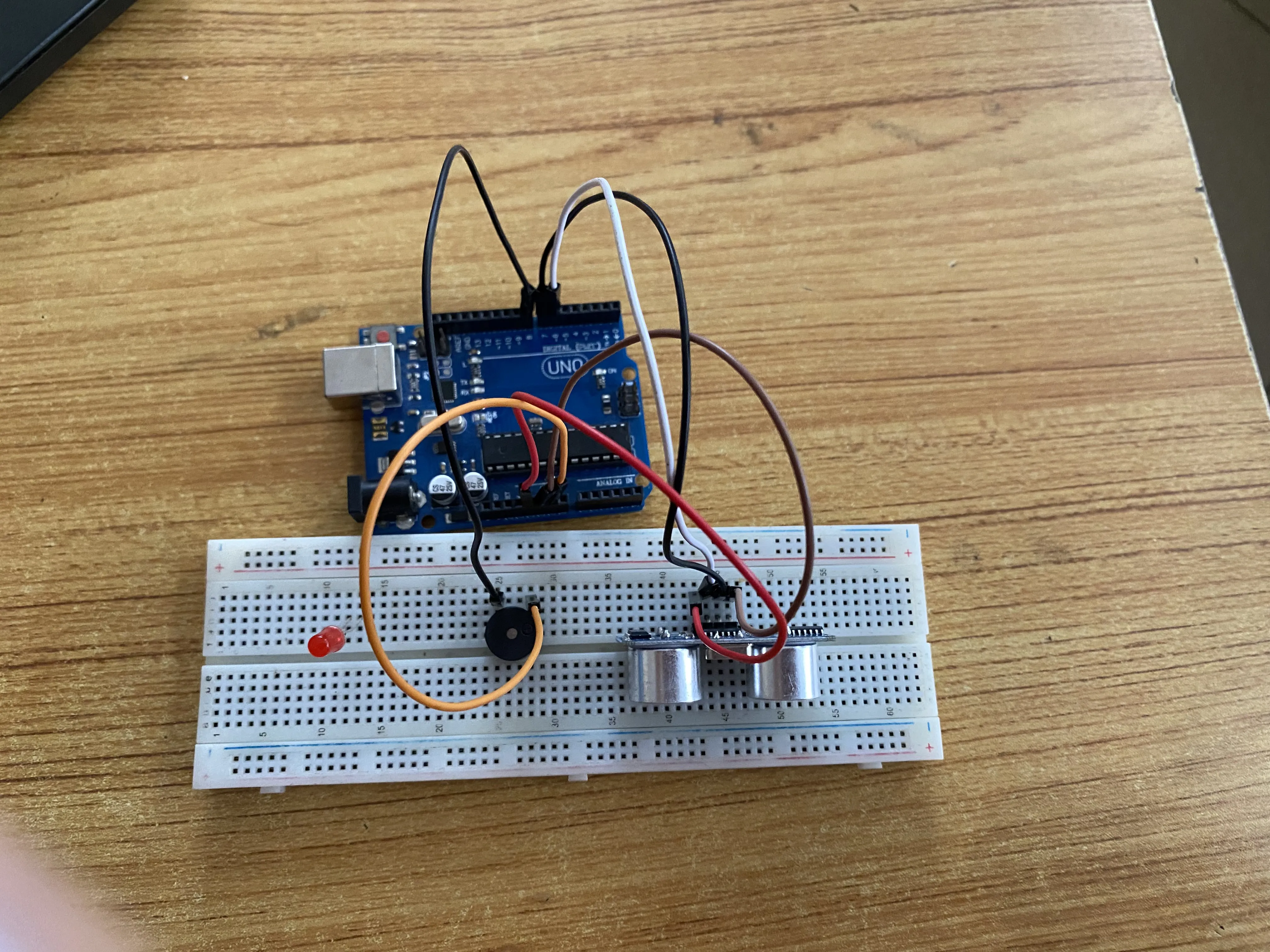
Step 6: Connect one end of the orange male-to-male jumper wire to the negative pin of the buzzer on the bread board to GND on the Arduino UNO.
 .
.
Step 7: Connect one end of the green male-to-male jumper wire to the positive pin of Red LED on the breadboard to digital pin number 9 on the Arduino UNO as shown below.
 .
.
Step 8: Connect one end of the blue male-to-male jumper wire to the negative pin of Red LED on the bread board to GND on the Arduino UNO.
 .
make sure you connect the arduino usb use blue cable to the Arduino board.
.
make sure you connect the arduino usb use blue cable to the Arduino board.
PROGRAMMING
Step 1: Open your Arduino IDE. See how to set up here: Getting Started.
``` cpp // Pin definitions const int trigPin = 6; const int echoPin = 7; const int redLEDPin = 9; const int buzzerPin = 8; const int distanceThreshold = 20; // Threshold in cm
void setup() { // put your setup code here, to run once: pinMode(trigPin, OUTPUT); pinMode(echoPin, INPUT); pinMode(redLEDPin, OUTPUT); pinMode(buzzerPin, OUTPUT); Serial.begin(9600); }
void loop() { // put your main code here, to run repeatedly: long duration; int distance;
// Trigger ultrasonic sensor digitalWrite(trigPin, LOW); delayMicroseconds(2); digitalWrite(trigPin, HIGH); delayMicroseconds(10); digitalWrite(trigPin, LOW);
// Read echo pin duration = pulseIn(echoPin, HIGH); distance = duration * 0.034 / 2;
// Check distance and activate alarm if (distance < distanceThreshold) { digitalWrite(redLEDPin, HIGH); tone(buzzerPin, 1000); } else { digitalWrite(redLEDPin, LOW); noTone(buzzerPin); }
delay(100); //Read the Serial monitor Serial.print(distance); Serial.println("cm"); delay(500); } ```
Step 4: Save your code. See the Getting Started section
Step 5: Select the arduino board and port See the Getting Started section:Selecting Arduino Board Type and Uploading your code.
Step 6: Upload your code.
CONCLUSION
This project provides a simple and effective way to enhance security using readily available components. It’s easy to set up and suitable for beginners.