Project 3.4.1: SMART STREET LIGHT SYSTEM
| Description | The Smart Street Light System is a simple project designed to automatically control lighting based on environmental conditions, such as light intensity. |
|---|---|
| Use case | This project finds utility in providing basic automatic and energy-efficient lighting tailored to specific needs. |
Components (Things You will need)
 |
 |
 |
 |
 |
 |
|---|---|---|---|---|---|
Building the circuit
Components Required:
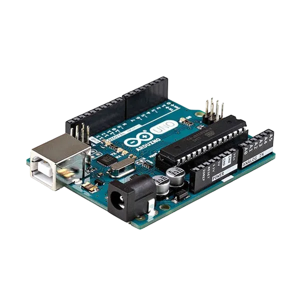
- Arduino Uno Board: 1
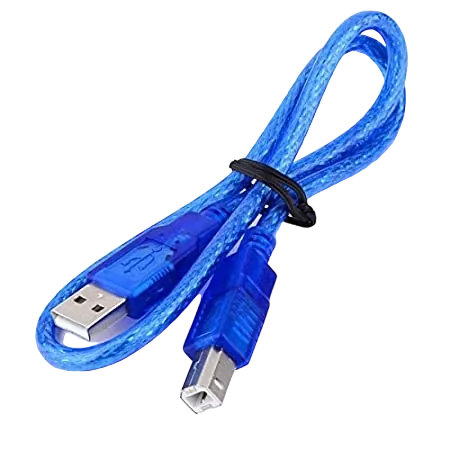
- Arduino USB Cable: 1
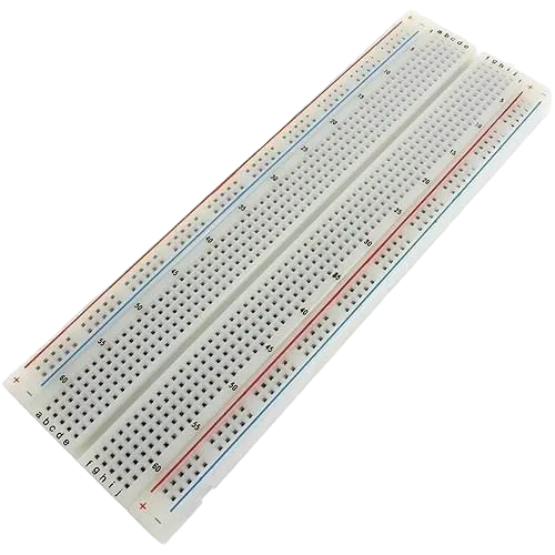
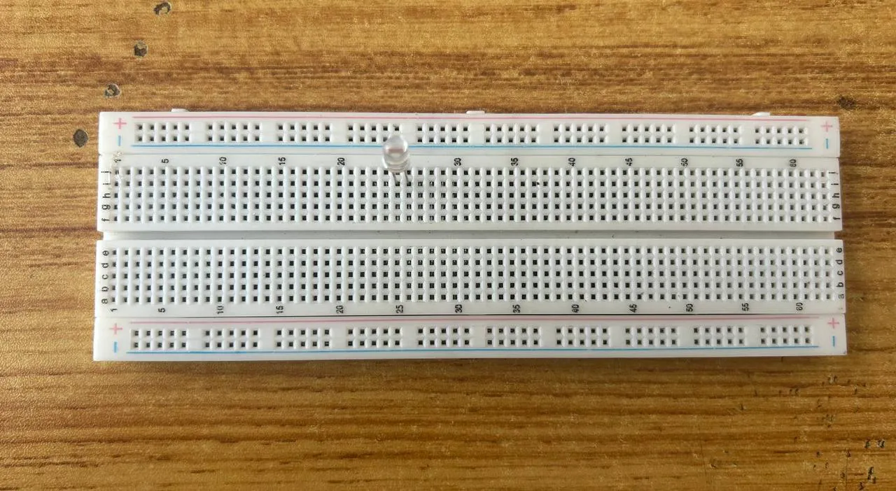
- Breadboard:1
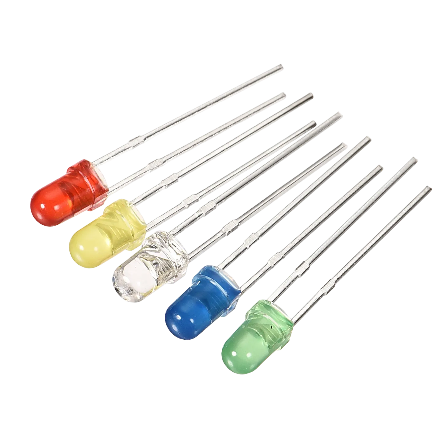
- White LED: 1
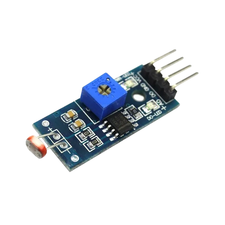
- Light Dependent Resistor(LDR) : 1
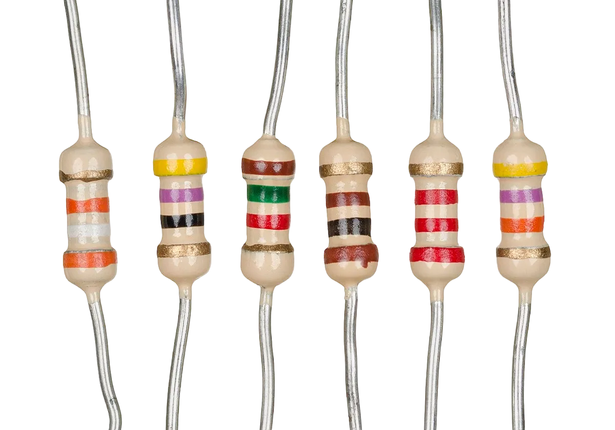
- Resistor : 1
- Jumper wire (red, blue, white and black male-to-male)
MOUNTING COMPONENTS ON THE BREADBOARD
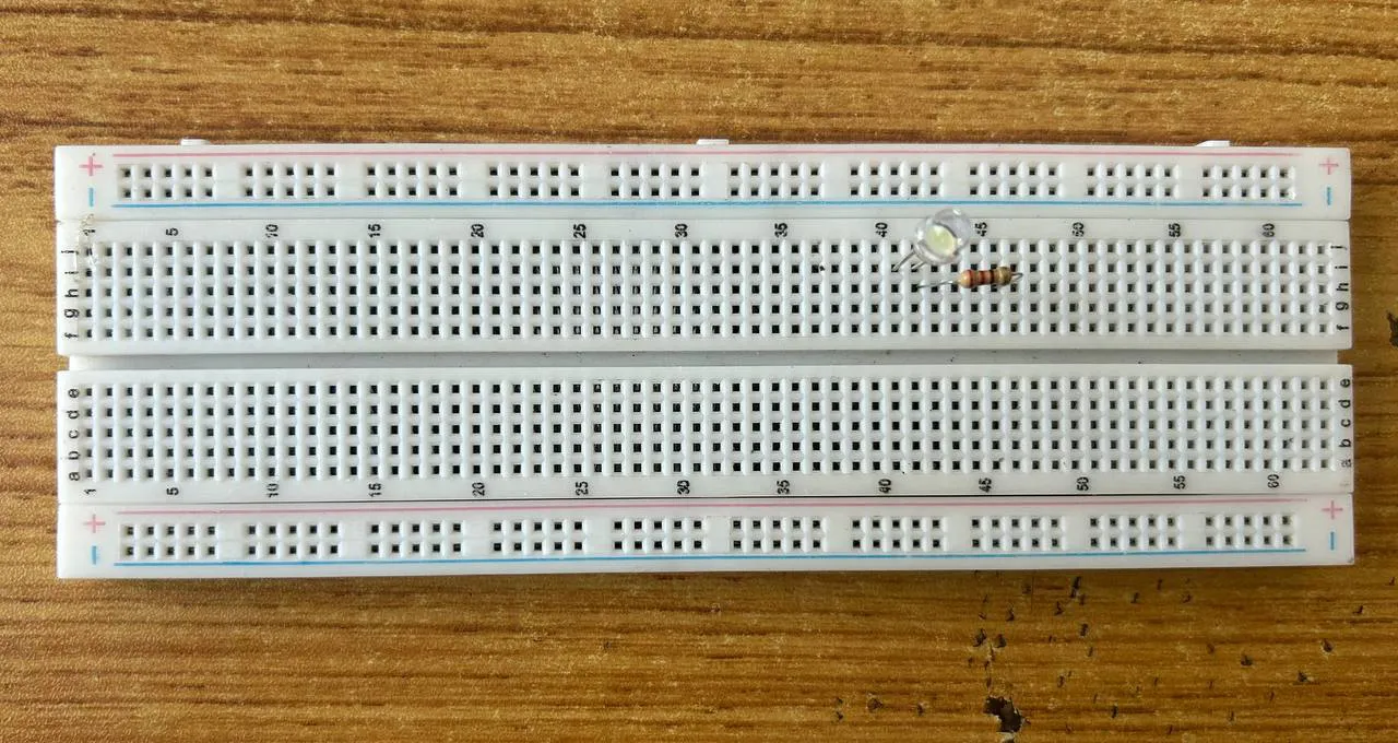
Step 1: Take the breadboard, and insert the white LED into the vertical connectors of the breadboard.
Step 2: Insert the resistor into the vertical connectors on the breadboard. Insert one side of the resistor under the positive pin of the LED on the breadboard.
Step 3 Insert the Light Dependent Resistor(LDR) into the vertical connectors of the breadboard.
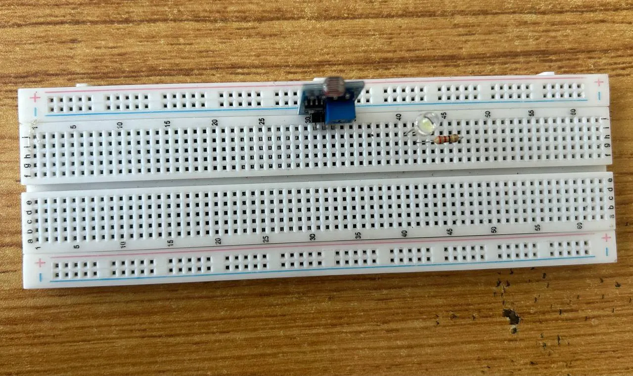
NB Make sure you identify where the positive pin (+) and the negative pin (-) is connected to on the breadboard. The longer pin of the LED is the positive pin and the shorter one, the negative PIN
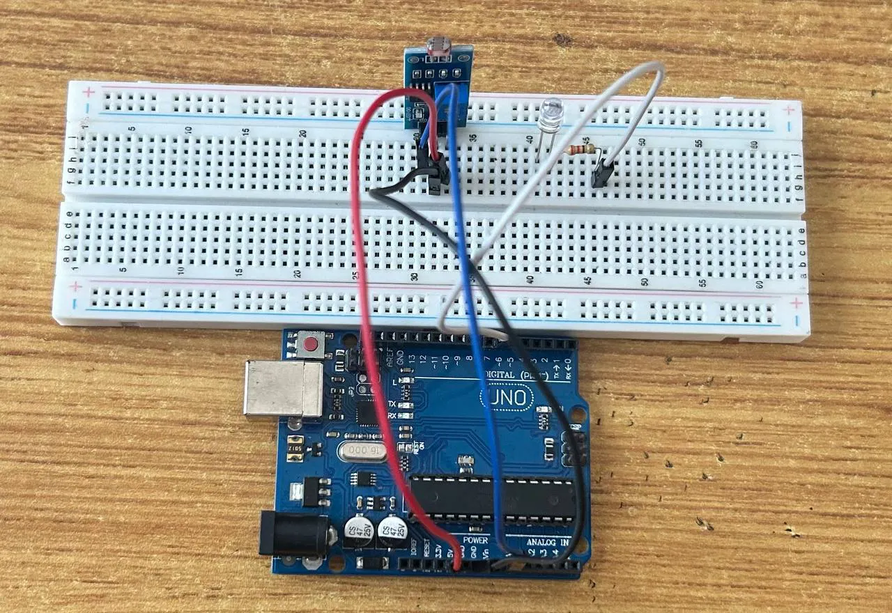
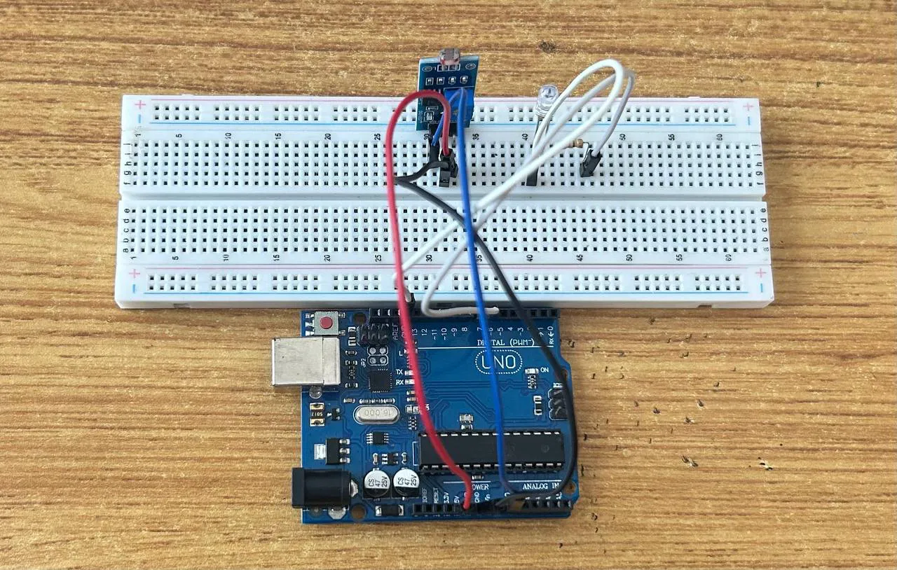
WIRING THE CIRCUIT
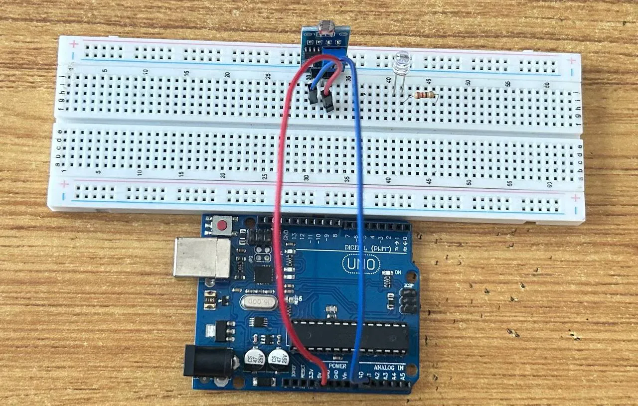
Step 1: : Connect one end of red male-to-male jumper wire to VCC of the LDR on the breadboard and the other end to 5V on the Arduino UNO board.
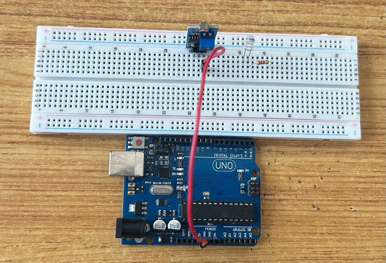
Step 2: : Connect one end of the blue male-to-male jumper to the OUTPUT of the LDR on the breadboard and the other end to A0 on the Arduino UNO board.
 .
.
Step 3: : Connect one end of the black male-to-male jumper to GND of the LDR on the breadboard and the other end to GND on the Arduino UNO board.
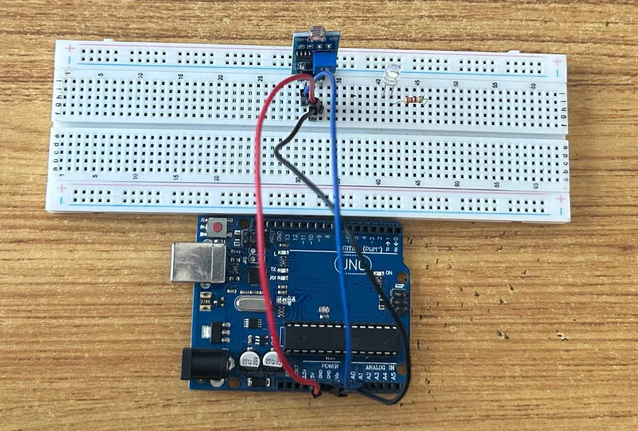 .
.
Step 4: Connect one end of the white male-to-male jumper wire to the positive pin of LED on the bread board to digital pin number 6 on the Arduino UNO board through the resistor as shown below.
 .
.
Step 5: Connect one end of the white male-to-male jumper wire to the negative pin of the LED on the breadboard and the other end to GND on the Arduino UNO.
 .
.
Make sure to connect the Arduino Board to the Laptop USB port using the USB cable in the Kit
PROGRAMMING
Step 1: Open your Arduino IDE. See how to set up here: Getting Started.
Step 2: Type the code into the Arduino IDE workspace
 const int ledPin = 6;

void setup() {
  // put your setup code here, to run once:
 pinMode(ledPin, OUTPUT);

 Serial.begin(9600);
  pinMode(ldrPin, INPUT);
}

void loop() {
  // put your main code here, to run repeatedly:
  int lightLevel = analogRead(ldrPin);

  Serial.print("Light Level: ");
  Serial.println(lightLevel);
  delay(500);

  if (lightLevel > 500) { // Adjust threshold based on your environment
    digitalWrite(ledPin, HIGH); // Turn LED on
  } else {
    digitalWrite(ledPin, LOW);

  }
   // Turn LED off
    delay(100);
  }
CONCLUSION
In a summary, the Smart Street Light project demonstrates a simple yet effective approach to automating lighting using Arduino. By utilizing an LDR to detect ambient light levels, this system can intelligently control LEDs, ensuring energy efficiency and convenience.